Tore My Rix SA-6B Apart

Please register or login

Welcome to ScubaBoard, the world's largest scuba diving community. Registration is not required to read the forums, but we encourage you to join. Joining has its benefits and enables you to participate in the discussions.

Benefits of registering include

  • Ability to post and comment on topics and discussions.
  • A Free photo gallery to share your dive photos with the world.
  • You can make this box go away

Joining is quick and easy. Log in or Register now!

Rob.

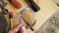
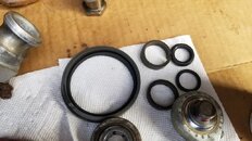
I let you know the part number of the original vendor SKF N 08 for a reason
Mil Spec components can be very expensive when not required.
Especially when you can obtain a standard commercial version off the shelf and local.

Regarding these two "salty" O-rings the standard ring is a $2 part. The advice was good going for the Teflon variant and that's a $10 adder but it's the the Mil Spec QA you don't need that doubled it. Iain

It's all good.. I whine and moan, but I ordered it all the same. I'm just a cheap SOB.

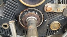
On that 1st stage liner above a very very light glaze bust cross hatch pattern should suffice.
Check the edge lip at the head end for wear but to me on the photo it looks fine

Change the rusty bolt out for stainless on that motor bracket support bar.

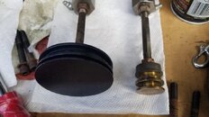
Take off the central spring bearing retaining plate (2 bolts) take a look at the spring wear on the backside of the plate ( lower bottom of the photo)

I will and I'll remove that plate and take pictures.

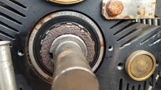
From this photo check the thrust rider trapeze Blue spring for movement on hand rotation
Change the bolt on the counter balance weight for stainless put it back the same way and not upside down or you will be chasing the compressor around the room from vibration

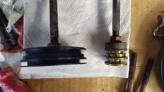
Also check those cooling coils very very carefully to ensure they are not touching especially underneath and that U shaped short return off the 3rd stage inlet from the 2nd stage separator where if fits between the coils on the 2nd stage discharge side. Iain

I'll check the blue spring for movement. I have checked it in the past (and greased the faces) and it's always been good. I will check the lines for any contact.

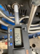
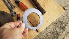
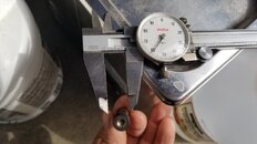
Its pretty easy with that SKF Spanner part number (I posted) without a torque wrench
to get 100 ft lbs its spin up the nut until the first gap lines up with the washer tab
Flywheel pulley drive side.

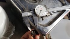
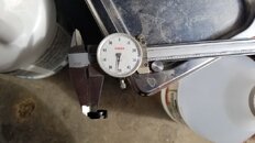
On the swash plate bearing side fan side its the second clear tab your aiming for
and a tad more arm strength. say around a 50 kg lift. Iain

This I don't understand at all, but I'll get in front of the unit and read it a few more times.

Sorry but the first 30 seconds of the 1st video was all wrong.
And that woman's voice on the second put me to sleep.

For a moment I thought I was is some Zen Guru ashram ******** vegan self help group with beads and open toe sandals contemplating my naval. Give me strength.

Well a lot of us around here were REALLY looking forward to a certain somebody to do it right and make a few more videos... but I guess he's drinking tea and playing with his grandson🙄

Thanks Iain. You're like the uncle I never knew I had that lives across the pond who calls to check in every once in a while.
 
I don't want to take the Reed valves out without having parts in hand to put each back together.
Hallelujah if only everyone did this before tearing stuff apart
Plan the maintenance and stick to the plan
Prepare for the unexpected and have a full spares kit to hand
Have the right tools to hand together with the workshop manual and not forgetting
Read the darn manual first and have the drawings out and open so you can see them.

These are the numbers for the liners

IMG_6695.jpeg
 

Attachments

  • IMG_6701.jpeg
    IMG_6701.jpeg
    72.7 KB · Views: 64
  • IMG_6700.jpeg
    IMG_6700.jpeg
    70.3 KB · Views: 66
  • IMG_6699.jpeg
    IMG_6699.jpeg
    75.4 KB · Views: 64
  • IMG_6691.jpeg
    IMG_6691.jpeg
    173.3 KB · Views: 71
Notice when you re ring the comp rings in the big main photo on previous post that both the leading edge and the trailing edge of each of the compression rings that knife edge lip is tucked inside the gap in the 0-ring between it and the metal piston side wall. Shown on the 1st stage as its easier to see than explain

This side of the pond requires that the new ringed piston be left to "set" inside a spare liner or when the liner is out of the block or when using a piston compressor tool to compress down and bed in before ramming it down into the liner on the compressor and damaging it. I will go into this in more detail later when I get time. Iain
 
This I don't understand at all, but I'll get in front of the unit and read it a few more times.
See what happens if you don't have the proper tools and then get the engineer to try and explain. Just kidding.
Look at the photo at the lock nut and tab washer

The Tab washer does two things.
1. It cannot turn because an internal tab that you can't see is recessed into the crankshaft keyway groove. This stops it rotating as you increase torque on the retaining Nut onto the shaft

2. its also acts as a marker start position.
So when you tighten up firm by hand only one of those external tabs will line up properly with the recess groove on the nut. You can see the tab peened over and centered properly on a torqued up tab in the photo attached.

Now you could peen over and locking tab on the washer into the nut recess at hand tight and the whole assembly will simply be locked at that hand tight position Don't as your only at hand tight.
Mark the start position tab if you like with a sharpie pen then just increase the torque until the 2nd tab or 3rd tab to its right is lined up and so on.

Or do like most of the customers I deal with IMHO is whack the heck out of it until it ain't going anywhere then bash the tab down with the side end of a screwdriver. Bless. Iain


IMG_6529.jpeg
 
If you do have a torque wrench the procedure is slightly different. You first obtain the proper torque setting
then rotate the crankshaft until you see a tab that is fully lined up and will fit into the nut recess and fold that tab over for a proper torque and lined up job.
 
See what happens if you don't have the proper tools and then get the engineer to try and explain. Just kidding.
Look at the photo at the lock nut and tab washer

The Tab washer does two things.
1. It cannot turn because an internal tab that you can't see is recessed into the crankshaft keyway groove. This stops it rotating as you increase torque on the retaining Nut onto the shaft

2. its also acts as a marker start position.
So when you tighten up firm by hand only one of those external tabs will line up properly with the recess groove on the nut. You can see the tab peened over and centered properly on a torqued up tab in the photo attached.

Now you could peen over and locking tab on the washer into the nut recess at hand tight and the whole assembly will simply be locked at that hand tight position Don't as your only at hand tight.
Mark the start position tab if you like with a sharpie pen then just increase the torque until the 2nd tab or 3rd tab to its right is lined up and so on.

Or do like most of the customers I deal with IMHO is whack the heck out of it until it ain't going anywhere then bash the tab down with the side end of a screwdriver. Bless. Iain


View attachment 806589
Ahhhhhh.. that makes sense. I'll match up what you just wrote with your post before.

I am going to try and figure a way to get the correct torque, but at least how I have a backup plan..

Thanks!!!
 
Well... Rix was nice enough to get back to me and is willing to ship out everything on 11/16 except for the 3rd stage rider rings (which are on backorder until 01/24). I think I would be ok using the ones I have until they ship as they're still within spec. I only pump about 1000cf / month, so it's not even like it would see a ton of use.

I measured the rider rings, they're at the lower end of there limit. My 3rd stage was still holding pressure unless I opened the bleeder, so I think I'm ok.

They're super easy to change out too.
 
@iain/hsm here are pictures with the plate and spring off
 

Attachments

  • 20231020_110657.jpg
    20231020_110657.jpg
    90.4 KB · Views: 67
  • 20231020_110833.jpg
    20231020_110833.jpg
    83.4 KB · Views: 61
  • 20231020_122956.jpg
    20231020_122956.jpg
    93.1 KB · Views: 62
  • 20231020_123002.jpg
    20231020_123002.jpg
    91 KB · Views: 60
And here are some pictures of some progress made today of tearing the pistons down and some cleaning;
 

Attachments

  • 20231020_122857.jpg
    20231020_122857.jpg
    59.4 KB · Views: 60
  • 20231020_122902.jpg
    20231020_122902.jpg
    75.5 KB · Views: 67
  • 20231020_122924.jpg
    20231020_122924.jpg
    74 KB · Views: 63
  • 20231020_123203.jpg
    20231020_123203.jpg
    56.1 KB · Views: 61
And here is some measurements on the 3rd stage rider rings and piston itself. The manual says

rider ring - .055 with .003 wear needed for replacement (mine is just a hair over .052, 1/2 way between .052 and .053)

floating piston - .558 with .003 wear needed for replacement (mine is consistently .559??)

I realize my micrometer isn't the best:(
 

Attachments

  • 20231020_123357.jpg
    20231020_123357.jpg
    53.4 KB · Views: 71
  • 20231020_123433.jpg
    20231020_123433.jpg
    59.9 KB · Views: 55
  • 20231020_123514.jpg
    20231020_123514.jpg
    53.4 KB · Views: 55
https://www.shearwater.com/products/peregrine/

Back
Top Bottom