Tore My Rix SA-6B Apart

Please register or login

Welcome to ScubaBoard, the world's largest scuba diving community. Registration is not required to read the forums, but we encourage you to join. Joining has its benefits and enables you to participate in the discussions.

Benefits of registering include

  • Ability to post and comment on topics and discussions.
  • A Free photo gallery to share your dive photos with the world.
  • You can make this box go away

Joining is quick and easy. Log in or Register now!

rob.mwpropane

ScubaBoard Supporter
Messages
4,825
Reaction score
4,944
Location
Fallston, Maryland
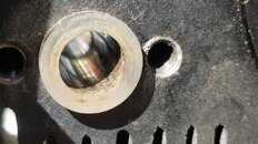
I tore my compressor apart for some maintinence. I've been meaning to do it for a while. Everything (to me) looks pretty good except for the top of the 3rd stage cylinder. Per the post linked below, Iain said the 3rd stage is made out of hardened steel. What can I do (if anything) to fix this? What could it be from? It looks like either some type of buildup or possible corrosion, but I'm not really sure.

If anyone has been following my other threads on the Rix I was having some blowby from the 2nd stage piston as well as some air leaking from the 3rd stage back into the 2nd. When I would turn it off I always got the blow by, but every onence in a while my 2nd stage OPV valve would also blow meaning the 3rd stage head was leaking some back into the 2nd stage. When running my 2nd stage pressure was just slightly above speck after ~ 3000psi.

@iain/hsm if you're there any guidance would be much appreciated!!!! Hope all is well with you!


Two options on the bronze liners, maybe three and yes you are right it's the 2nd stage in the photo.

First option with the bronze liner is leave them alone that allows the PTFE film that has been deposited onto the liner to increase the tribology factor and reduce the friction factor.

Option two: Just "glaze bust" the surface of the liner with a light wet 600-1200 grit paper on your finger
and achieve a cross hatch patching right turn in, left turn out. LIGHTLY

This removes the "glaze" and makes fresh microscopic grooves for the PTFE off the compression and rider ring to fill and achieve a better surface dynamic by having both the piston and the liner in effect PTFE coated. This is the preferred method but needs care.

Option three is using a small cylinder honeing tool a bit over kill but ensures concentricity and a linear bore.

The in the field method is number two by finger and no gloves using a 1200 grit wet and dry. When you burn your finger you know your either rubbing too hard or been at it too long or your putting too much pressure on the side walls.

While you are at it with old compressors I have assumed you have first taken the head off and have a clear hole through the liner each stage, easier to clean out after your done, easier to inspect.

But most important is to run your finger if you have the skin still on and not blistered down the bore on stages 1 and 2 especially at the point where the piston stops at TDC (Top dead centre) and feel if there is a worn ridge around the inside of the piston liner.

We would use a 3 point bore micrometer in the workshop to measure this but I'm aware this is not in our Field Service Manual and way to expensive tools for home builders so you need to judge for any wear in the liner or excess in concentricity by feel.

From memory its a 3M 7447 scotch bright rectangular pad Aluminium oxide brown in colour and a little water nothing else, clean with a wet clean paper towel and dry using dry paper or just leave to dry

The 3rd stage liner is an expensive hardened steel cylinder ground to a very high tolerance and heat treated hardened. I would leave it alone and don't dick with it.

I will keep this to just In the Field Service stuff and using simple hand tools but for context we would in the workshop also do a PMI (positive material inspection) on the hard metal pressure parts just to ensure the clients didn't stick on the odd nut and bolt part out of Home Depot.

PHOTOS Shows a Thermo Fisher SCIENTIFIC Portable x-ray positive material identification tool we use on the parts, in effect an x ray of the parts showing the material content and comparing the results with a "library" of our know parts of materials used. Its not that good as a alcohol breath test analyser.

View attachment 762564
 

Attachments

  • 20231013_130637.jpg
    20231013_130637.jpg
    102.3 KB · Views: 107
Hi Rob

You caught me at a good time at work drinking coffee and a bun. Its sadly becoming our Sunday service due to client pressure.

Not much of a problem on your liner, its corrosion at top dead centre TDC.
The HSM Military In Process Service Procedure for the SA-6 (not for public publication)
sort of says. A light wet and dry or a Dremel stainless 530 brush wheel to remove the lumps and
not to go any further down the liner onto the smooth wall. In other words don't ream the whole thing

The reason its not much of a problem is that the piston never gets that far up the liner and
the 30 thou clearance from TDC to hitting the base of the head is cleared further by the piston end rider ring and piston grooving so the important bit (the polymer) leading piston ring is well enough behind all that corrosion to cause any damage.

Further more you will note there are two (2) pressure breaker rings in front of the leading edge compression ring on that 3rd stage piston giving you an even larger clearance from that rusted stuff before the important compression rings can be affected.

You could omit the two pressure breaker rings and fit new compression rings instead if you like, lasts a tad longer it's a dollar and cents call. Also fit the two least worn compression rings in place of the pressure breaker rings but again that's not advised for the few quid they cost and you would need a micrometer to measure

It's in the design philosophy, minimum tools needed to service. So a bit of a conflict

In addition consider that the piston ring by contrast is soft (metal wise) so the idea was to let the piston wear our as it was (then) cheap rather than score the expensive (by comparison) heat treated stainless liners

For the future if there ever is a commercial sports version of the SA-6 then consideration away from the precipitation hardened stainless options to a more commercial available stainless would be considered and changing the piston itself slightly away from the brass end and up the metal spec into to bronze silicone or a aluminium bronze component would be a future consideration.

Price would also have to come down if making it as a commercial product than the excessive IPP for the military.

The military still use for this block for the sidewinder missile `program at our end of the pond while you lot used it with the SEAL teams. Not many sidewinders used in action now a days at our end and the SEAL's that used the SA-6 have mostly all retired.

My job eventually will be to put the cat out, lock all the doors and switch off the lights on the SA range But when I'm done, never say never. Iain
You are the man! Really brightened my day. What would cause the corrosion and how come it's not in any of the other cylinders?

Here's a link to all my pictures I took (if you're willing to take a look). I'm replacing all o rings, gaskets, rider rings, and compression rings while I have it apart. Scubaboard is limited to one picture per post, hence the link.

One thing I did notice is the 3rd stage came out very easily, a lot easier then I thought it would. Very easy to slip back in too. I don't think it was leaking as pressure was still building @ 5cfm whenever I timed it. Maybe starting to wear out? Maybe just dirty?

It's our 4 o clock Tea Break here in the UK so:

1. Corrosion is caused by water vapour condensing into water condensate in that liner.
To reduce this your supposed to run the compressor with the drain valves open starting with the 2nd stage
for a few seconds to ensure all the water condensate droplets and drizzle has been removed
Then all you're left with is water vapour.

And this "potential water vapour condensing into water condensate is further reduced by the compressor running without load due to the factor that an increase in pressure also increases the condensate loading. Hence the consideration of the back pressure regulator (BPR) set at around 1500 psi as most vapour under pressure will condense out of an oil free compressor as all the cooling over the heat exchanger coils condenses more of the water vapour into liquid form and is easy to separate unlike a typical oil lubricated compressor that the hot oil is harder to cool hence more vapour is carried over for the chemical cartridge to deal with.

Another positive point for the SA oil free compressor over an conventional oil lubricated compressor is that less water vapour can carry over on an oil free oil less compressor and this allows a same size filter chemical stack to last longer. This effect is further enhanced by the oil mist not coating each of the molecular sieve balls or matrix with a thin oil film acting as a seal on the chemical matrix. Basically rendering that portion of the chemical useless. Allowing a 250 hour filter life on a standard 33 inch filter stack for the SA-6 against for the same filter used on an oil lube compressor allowing only 40 to a 50 hour of cartridge life. (Under our more stringent UK/EU allowable oil standards for breathing air.)

Deeper down the rabbit hole than I would have liked. Tea break over, back on our heads. Iain
 
It's our 4 o clock Tea Break here in the UK so:

1. Corrosion is caused by water vapour condensing into water condensate in that liner.
To reduce this your supposed to run the compressor with the drain valves open starting with the 2nd stage
for a few seconds to ensure all the water condensate droplets and drizzle has been removed
Then all you're left with is water vapour.

Ok, so run the compressor as normal (my PMV is set to 2000), then shut valves off and open 2nd stage drain, then 3rd stage drain, then turn off?

I always idled the engine down, turned off, then bled 2nd and 3rd drains.

Also, I don't think the corrosion is so much from me as it is from the previous owner. I haven't even put 50 hours on it.

Any idea why 3rd stage was so easy to slip in / out? Dirty? Worn? Or something else? (I used a pencil to push it out and back in the fan side, I did not need the 3rd stage tool that I do have).

As always, thanks Iain!!!
 
Hang fire on your servicing I could go through the pictures when I get time if you like.

For one I would replace all those head bolts with 303 stainless ( I can give you the sizes)
and also replace the bearing lock nuts and washers

You also IMHO need a couple of SKF Lock Nuts Part No N08
and two Lock Nut Washers (for a keyway shaft) Part no SKF W08
Also maybe useful buying a mounting tool SKF part no HN 8-9

We have a `"HSM Special" a lock nut tool for the SA Mil Spec variants that allows to
get the correct and verified torque 100 ft/ lbs and the 200 ft/lbs torque on each end
Its basically a Trailer/Truck wheel hub socket for a 1/2 drive wrench wrench bar cut in half
with each half welded onto a steel tube pup piece that allows it to reach over the fan shaft and drive shaft
lengths at each end on the compressor. A small PTFE dowel piece inside gives the 1 inch clearance for the shafts and stops the socket slipping off when your pushing for the 200 ft /lb torque click.

Further if you have a new replacement lock nut you can be forgiven for "thrapesing" off the nuts with a cold chisel and a 5lb lump hammer (not in the manual)

Use an adjustable spanner (Cresent Wrench) to hold the shaft in position while wacking the thing

If your rich and single its a Snap-on VS4652 USA 1-5/16" Spanner. Known to you lot as a wrench.

Don't hit the threads ever with said chisel or hammer cover them with duct tape and string to loosen and use a lot of WD40 to release the rust hold at least the day before to give it time to penetrate. Iain

My bearings are actually looking like they're seeping a little. Shaft feels rock solid for now. Do you have a reference number (besides what's in the manual). Apparently Rix wants $500 for ONE bearing which is a little out of this world (for me anyway).
 
My bearings are actually looking like they're seeping a little. Shaft feels rock solid for now. Do you have a reference number (besides what's in the manual). Apparently Rix wants $500 for ONE bearing which is a little out of this world (for me anyway).
Rob

Seeping grease around the rubber seals is OK. The grease is over packed and not your standard grease.
Now as for the $500 you will need to tell us what part number you were quoted
also did it include shipping, minimum order charge, expedited fee etc, that sort of thing

There are five (5) standard (ish) bearings on the SA-6
One (1) for the swash Plate, Fan side holding the rod end bearings (grease out at the back is common)
Two (2) for the thrust Rider, Fan side at 6 o clock position, grease these externally to the thrust rider plate
And two (2) internal holding the crankshaft, These are special with a flat ground across the outer race
to locate the dog tooth bolt and stop the outer race from ever spinning in the aluminium block.
This adds considerably to any off the shelf cost to remanufacture and its a precision ground flat.

In addition three (3) Rod end Bearings for each of the pistons. Also special re machined items

Another high end cost is the specific grease that's used. Again its a special with long lead times, high volume required orders and high minimum order costs
Each of the bearings in question have to be to modified from OTS manufactured then re cleaned re inspected re greased and re sealed. Its an expensive option

Question is I guess is it worth it for a light duty recreational scuba use? IMHO no it's not and another indication of the engineering considerations if the SA was offered as a commercial only scuba product. Iain
 
Yes Sir, it is the 2 bearings on the shaft. I don't think they're bad yet. It was only mild seepage
 
For comparison the UK built SA-6 units that I have built had a verified main crankshaft life of about 8500 hours running. This is a verified life with the SA-6 UK builds verified in a couple of named UK dive shops.
8500 Hours running is filling around 35,000 Standard scuba 80's
and at £3 a fill ($4) a fill that's a considerable return on a dive shops investment.
Further the lack of any oil used in that 8500 running saved the 30 odd oil changes at £40 ($50) a time

Compare that to the some 30 to 42 oil changes others here would have required say at £40 ($50) a time

Also in addition consider the some 200 to 250 hours use out of the standard 3lb repack cartridge
at £15 ($18) a time needing 42 filter changes £630 ($775)

Consider the same repack at the more normal oil lubricated compressor requiring an oil change every 50 to 60 hours and your up around the 270 filter cartridge change outs over the same period .

Make you wonder the power of advertising and those guru diver endorsements I guess. Iain
 

Back
Top Bottom