Gosh you have a good memory! These were the last thing I needed, they were on backorder for 3 months

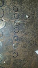
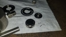
These are the "pressure breaker rings". Each is a set of 2 pieces, they go around the piston like a 1/2 moon on each side. Part # 18-C1603-4.5P (my picture is backwards from this diagram, but you get it)
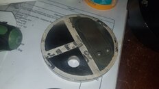
In regards to the 1st stage, I looked at pictures when I took it apart. That gap had nothing, but I'd like clarification on what it does before I put it back together. If you handed me the parts I would have thought the o ring should go in the gap. It even feels weird with the compression ring pushed out and the rider ring more in the groove below the compression ring. You can kind of see what I'm talking about in the picture I posted.
View attachment 830648


 Iain
Iain