Tore My Rix SA-6B Apart

Please register or login

Welcome to ScubaBoard, the world's largest scuba diving community. Registration is not required to read the forums, but we encourage you to join. Joining has its benefits and enables you to participate in the discussions.

Benefits of registering include

  • Ability to post and comment on topics and discussions.
  • A Free photo gallery to share your dive photos with the world.
  • You can make this box go away

Joining is quick and easy. Log in or Register now!

Darn right there's a chance.
What with free Gym membership and all the overtime you want what's not to like
As for you lot Hope dies last. LOL
You know if one of those mysteriously found it's way over here to rust away that sure would be nice!

Why do some rod ends look blue vs stainless steel? Or maybe it's lighting?
 
Nice and not going to happen are two distinctly different outcomes.
We do tend to dream a little big over here
 
HSM Engineering
Unit 1. Block B. Crab Apple Way
Vale Business Park
Evesham. England UK
WR11 1GP

Mobile: 07801 340096

Rumor has it he got fed up waiting for Rob's SA-6 parts to arrive to continue the thread
and got bored so made up half a dozen while he was waiting for the tea to brew. LOL

View attachment 810899
@iain/hsm in my mind the internals (for the 1st stage, correct?) laying next to these in the picture are out of place? Do you build the stages before you mount the unit? I would think you would bolt those on last?

Just curious.
 
Good day all, finally getting around to the rebuild. I have a few issues / questions. Maybe @iain/hsm can chime in.

1st issue;

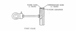
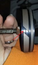
The 1st stage piston states there is supposed to be a rider ring, a compression ring, and an o ring expander. This is how mine came apart. The diagram shows the 3 rings. On my piston there is a groove below the rider ring. I'm not sure if this is supposed to get another o ring expander or if it just stays empty? In the picture that I took I have it setup the way it is in the diagram, but I am questioning what that other groove is for?
Capture22.JPG
Capture222.JPG


2nd issue;

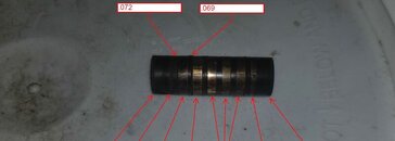
On the 3rd stage piston there are grooves for the "pressure breaker rings". On my piston the gap measures .072 amd .069 (as seen in the picture). The old pressure breaker rings measure .069, the new ones measure .0715-.075. I can get them to fit in the groove that measures .072 but there's no way they'll fit in the groove that measures .069. I'm thinking maybe these are out of tolerance from the manufacturer? Maybe the piston is out of tolerance?

Not sure if I could lightly sand these down to fit or what the protocol is?

I could not find anywhere in any literature what any of these are supposed to measure.

If it matters old rings thickness measure .069, .069, .069, .0695
New rings thickness measure .0715, .0715, .072 and one came in at .075!
Capture223.JPG
 
[snip]
If it matters old rings thickness measure .069, .069, .069, .0695
New rings thickness measure .0715, .0715, .072 and one came in at .075! Are we talking Compression Rings here?
[snip]
^^^^^^^ Spitballing ... maybe there is a specific thickness loading order to maximize lifetime.


I would suggest reaching out to RIX with ALL of this info.

If the parts are correct-spec, there should be a service bulletin released on how to deal with them (I don't see anything in the manuals either).

If they are out of spec, RIX needs to get on it ASAP for everybody's sake.

Weren't these third-stage rings what you had to wait for? New supplier, new machinery, rushed QC ????????


No Idea on the first stage.
Gosh you have a good memory! These were the last thing I needed, they were on backorder for 3 months:(

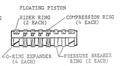
These are the "pressure breaker rings". Each is a set of 2 pieces, they go around the piston like a 1/2 moon on each side. Part # 18-C1603-4.5P (my picture is backwards from this diagram, but you get it)

In regards to the 1st stage, I looked at pictures when I took it apart. That gap had nothing, but I'd like clarification on what it does before I put it back together. If you handed me the parts I would have thought the o ring should go in the gap. It even feels weird with the compression ring pushed out and the rider ring more in the groove below the compression ring. You can kind of see what I'm talking about in the picture I posted.

Capture224.JPG
 
Going through my photos so you don't have to pull mine apart for a stare & compare :eek::wink: :rofl3: (note see DM, too)

I cropped and adjusted trying to see if there is anything under the 1st stage rider. It doesn't look like it to me but pics are attached.
IMG_20230228_142003794.jpg

IMG_20230228_142053887.jpg
 
Going through my photos so you don't have to pull mine apart for a stare & compare :eek::wink: :rofl3: (note see DM, too)

I cropped and adjusted trying to see if there is anything under the 1st stage rider. It doesn't look like it to me but pic are attached.
View attachment 830649
View attachment 830650
It's odd. At least I noticed it and didn't just try putting it together (like I normally do, LOL). I'm sure there's an engineering reason that I just can't "see".

Your Rix is so much prettier than mine, LOL.
 
In regards to the 1st stage, I looked at pictures when I took it apart. That gap had nothing, but I'd like clarification on what it does before I put it back together. If you handed me the parts I would have thought the o ring should go in the gap. It even feels weird with the compression ring pushed out and the rider ring more in the groove below the compression ring. You can kind of see what I'm talking about in the picture I posted.

Well, the compression ring should be applying significant pressure against the cylinder wall to provide a seal ,and the oring between the piston and compression ring seals that gap in addition to providing radial expansion of the ring.

My off-the-cuff thought is that rider ring fundamentally functions to keep the piston from banging around when the compression ring wears or fails. It may also aid in keeping things aligned.

Pretty yes, but I'll probably spend a buttload of hours and more $ than the factory part creating my shroud SYSTEM.
 

Back
Top Bottom