Joining the 109 Club

Please register or login

Welcome to ScubaBoard, the world's largest scuba diving community. Registration is not required to read the forums, but we encourage you to join. Joining has its benefits and enables you to participate in the discussions.

Benefits of registering include

  • Ability to post and comment on topics and discussions.
  • A Free photo gallery to share your dive photos with the world.
  • You can make this box go away

Joining is quick and easy. Log in or Register now!

Once all is said and done, Ill compare it to my g500, my current primary, and see what is worth keeping where. I like the idea of having the metal regulator to collect come moisture.
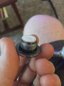
The poppet is one of the things that concerns me. So attached is the poppet that came out. I believe that this is the older style poppet, is that correct?
View attachment 366586

You might end up getting another 109 and retiring the G500, but it's also an excellent 2nd stage. The poppet in your photo is the old one. I'm sure the upgrade kit from vdh has a new poppet.

The lever issue can also be about the height, I think herman makes a tool to adjust that. Basically, get the orifice adjusted so that it just barely does not flow with the diaphragm off. Then put the diaphragm, cover, and clamp in place (don't tighten the screws) and see if it flows; usually you'll have to tighten the orifice a bit, which drops the lever. If it's a small adjustment, like 1/4 turn or so, you're fine, but if it's a lot that means that the lever is sitting too high and the foot angle needs to be increased. Otherwise you'd have a much higher-than-necessary cracking effort just to put the lever at the correct height.

I've never adjusted foot angle on the levers, I just buy the new lever that has the curved feet. It has worked perfectly for me.
 
Also waiting on my new book "SCUBA Regulator Maintenance and Repair"

While you are waiting on your book and parts, you can (and should) download the pertinent manuals at www.vintagedoublehose.com. It would also behoove you to download the file named "scubapro poppet changes" from the same location.

www.vintagedoublehose.com-->Manuals and Catatlogs-->Continue-->BLPEN163-->ScubaPro Schematics. Download the following files: ScubaPro poppet changes, G250 Vintage annotated schematic, 109 250 adjustment principals.
 
Alright, its been a while, but I have received my rebuild kits for both the mk10, the 109 with conversion, Harlow's regulator book and have rebuilt both. came across two things I am needing help with.
The first is with the 109 balanced adjustable kit, I was not able to assemble it with the spring between the spring block, and the adjuster, so I assumed that it was not meant to go there, but it was meant to go on the stem between the poppet and the block? I assumed that that is where the balancing came from be allowing air pressure to go through the stem to push on the spring black.
The second thing is when I connect the mk10 up to a tank, I get air blowing out of the HP seat carrier. Is there a way to tell where I missed something?
 
here is what it should be like when assembled correctly
upload_2016-2-14_8-41-27.png
:

As to the MK-10 did you install the stem o-ring and piston using the bullet tool? If you didn't, you risked cutting the stem o-ring with the sharp edge of the piston stem........
 
I was not able to assemble it with the spring between the spring block, and the adjuster, so I assumed that it was not meant to go there, but it was meant to go on the stem between the poppet and the block? I assumed that that is where the balancing came from be allowing air pressure to go through the stem to push on the spring black.
The second thing is when I connect the mk10 up to a tank, I get air blowing out of the HP seat carrier. Is there a way to tell where I missed something?

The cutaway photo posted by rhwestfall shows the correct assembly, that's a very useful photo BTW! The balancing air goes through the poppet stem and pressurizes in the balance chamber. (I think what you are calling the spring block is actually the balance chamber) Since the chamber is held in place against the adjuster, the pressurized air pushes the poppet against the seat, working with the mechanical spring.

On your MK10, you almost certainly don't have the o-ring that seals the HP seat installed correctly. SP replaced that o-ring with a thick red washer to make this a more idiot-proof process. (I'm NOT calling you an idiot!:D) Anyhow, you have to firmly seat the 013 o-ring in the regulator body before screwing in the seat retainer. You can use a pencil eraser, maybe find a socket that's the right size, I sometimes use the blunt end of a chopstick or the handle end of an o-ring pick. Just make sure it's set in place and centered. Then screw in the seat retainer and try again.
 
I did not use the piston bullet, I plan to turn one down on the lathe at work because I am cheap. While pushing it in, I used light pressure and slowly rocked the piston in circles until it fell into place. I don't think that is where my leak is coming from because that would allow high pressure to go to the ambient pressure and blow out the environment holes.
I will take apart the mk10 and see how that looks.
It looks like I have the 109 assembled properly.
 
I did not use the piston bullet, Always use the right tool. I plan to turn one down on the lathe at work because I am cheap. While pushing it in, I used light pressure and slowly rocked the piston in circles until it fell into place... Not a good idea
MK 10.JPG
.. I don't think that is where my leak is coming from because that would allow high pressure to go to the ambient pressure and blow out the environment holes.
He is referring to #4 not #9
 
One of the issues of not using a bullet is that you are never SURE you didn't put a tiny nick in the seal. A small anomaly may not see a leak right away, but given time it may manifest itself at the most inopportune moment.

Making your own bullet is certainly in the DIY spirit. For those who want to leave that chore to someone else, I can recommend the tools made by Herman.

Here are links to a couple of reviews I've done of his handy work.

ScubaPro Lever Height Adjustment Tool review

Custom Scuba Tools MK 5 and MK 10 Piston Stem O-ring Tool

BTW The high pressure seat -013 o-ring, Halo mentioned (which is the problem) can be seated with a 3/8" nut driver. Lightly lube the o-ring and press it in place with the tool. For more information download the annotated file from www.vintagedoublehose.com and read the "Special Engineering Notes" on page 2 of that document.
 
Last edited:
I love the 109, and have serviced and use several of them, both balanced and unbalanced, but have yet to have any of them on a ScubaPro 1st. Is this a faux pas?


Bob
Initially I too was only interested in the 109/156's, but read enough strong support for the virtues of the MK 5 1st stage that I went ahead and bought a number of them as well to use with my 109/156's, the MK 5's are said to be very simple, robust, reliable and competitive with 'modern' 1st stages performance wise.
 
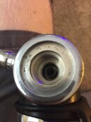
Ok, I think I found my problem, and its because I am an idiot. I missed an o-ring I believe. I do not have an o-ring installed between the -4 o-ring in place. Missed that one.

IMG_4419.jpg IMG_4420.jpg
 

Back
Top Bottom