Conshelf Supreme first stage?

Please register or login

Welcome to ScubaBoard, the world's largest scuba diving community. Registration is not required to read the forums, but we encourage you to join. Joining has its benefits and enables you to participate in the discussions.

Benefits of registering include

  • Ability to post and comment on topics and discussions.
  • A Free photo gallery to share your dive photos with the world.
  • You can make this box go away

Joining is quick and easy. Log in or Register now!

I think Luis is right about the second stage being more important for WOB and first stage IP drop playing a bigger part than the flow rate. I seem to recall reading a number of times way back about people over-breathing regulators, particularly at depth. I have read more recently reviewers make comments about far regs have come in terms of breathing performance in the last 20 years! The curious thing is that when you look at the numbers there doesn't to be much difference.
Take for example the Conshelf first stage, I have seen the flow rate quoted as about 50 scfm and this unit has been around for nearly 40 years (AFAIK). The new Titan first stage combined with a Titan LX second stage has been described as a good breather with very good reserves for deepish diving, well turns out that (according to an Aqualung website I found) it's flow rate is 1450 L/min which equates to about 50 scfm, the same as the Conshelf. Even the new top of the line Aqualung Legend first stage is only a smidge more- under 60 scfm! The Poseidon Xstream first stage is toted as a deep technical unit- for use to 200m on trimix, it's flow rate is about 76 scfm and the older Cyclon wasn't much more than half this.
Of course we all know that Scubapro quotes huge flow rates for their first stages but does it really make any difference when the US Navy manual says that a super fit naval diver doing "severe work" uses about 1.9 to 3.5 cfm (presumably at the surface). In fact I'll bet that Scubapro's (and maybe all manufacturers) flow rates are based on the combined flow of all the low pressure ports venting simultaneously when really what counts is the flow that is delivered to the primary first stage and how little IP drop there is during the cycle. It may also be that the number of low pressure ports a first stage has (5 on the MK25 and 3 on the Conshelf) has a bearing on the flow rate figure?
Anyway, I tried out a Conshelf XIV second today on a Mares MR22 first and it worked really well- maybe the Mares DFC (first stage venturi effect) really does work, but that is probably another thread on a different forum?
 
Luis and Rob,

This is a very interesting discussion. I would like to add two points.

UDS-1diagram.jpg

First, I have a UDS-1 diving system by U.S. Divers Company from the 1980s. Unfortunately, I cannot now dive it as it has one-inch openings on the three aluminum cylinders, and nobody has an eddy current tester for it. So I cannot get the cylinders hydroed and therefore the unit filled. But, I have dived it many times, and this unit has the largest openings of any unit for air flow. The first stage, Conshelf-style first stage built into the triple cylinder valve. Because of this design, there is no regulator/valve interface, and the openings are very, very large.
UDS-1manifoldreserveend1.jpg

The Scubapro A.I.R. I regulator has the ability to use two hoses going into the second stage.
AIR-1AddendumFigure1.jpg

This allows the use of two regulators, with a doubling effectively of the surface area for the openings and a doubling of the volume of the two hoses, both of which decreases the interstage pressure drop. Here is the Scubapro graph of the breathing cycle of the A.I.R. I:
AIR-1SecondStagePerformance.jpg


I combined these two concepts, and mated the A.I.R. I with the UDS-1.
UDS1bal.jpg

At one point I took it one step further, and used two hoses on the LP side of the UDS-1 (there is an auxiliary port for a tool, which I used that comes from the manifold) into the A.I.R. I second stage. That was amazing as a breathing machine. Even with the USD second stage, I could breath this unit down to zero gauge pressure before feeling a breathing resistance.

SeaRat
 
This AIR1 stuff is great data. And I think it gives us half of the answer we're looking for. I'm not sure we need a WOB loop to answer the rest of this question, and your AIR1 loops tell us why.

First, a roughly sinusoidal breathing pattern isn't too far off. It just needs to be squared a little bit. The point is that as you inhale a big (2 litre) breath, it starts slowly, accelerates, plateaus and ends. Then exhalation starts, but we'll ignore that. So if inspiration is half of a breathing cycle, the accelerated portion of an inhaled breath is perhaps 80% of that half cycle, or 40% of a full breathing cycle.

Let's do a little math for a heavy exertion situation:
Big guy breathing 50 breaths per minute (and he can't keep that up for long, but we want to see what his equipment does). What is the max flow rate during inhalation?
50 bpm = 1.2 sec per breath cycle.
If the accelerated inhalation (max flow) is 40% of the cycle, then the max flow portion takes .4 x 1.2 or .48 sec.
Let's assume our big guy is able to take in 80% of his breath during the accelerated portion, and only 20% is inhaled during the slower beginning and end of an inhaled breath. I'm being generous with this sine wave. Eighty percent of his 2 liter breath is 1.6 liters.

So the maximum flow (at the surface) for this big guy is 1.6 liters in 0.48 sec.
That computes out to 200 liters/minute, or 7 SCFM. This fits quite nicely into the data quoted above about the super fit Navy diver consuming 1.9 to 3.5 SCFM. Since he's inhaling 40% of that time, his max flow is 3.5 SCFM divided by 0.4 or 8.75 SCFM max flow. This tells us that our flow guess is about right.

Now let's look at a part of that wonderful AIR1 data above. Look at the top right quadrant of either set of blue loops. As the depth increases, the air gets thicker, and the venturi effects become more pronounced. At the surface, it takes 4 SCFM to pull the reg from a sucking inspiratory effort over into freeflow with a 2000 psi tank. At 100 feet, the thicker air generates a more vigorous venturi effect and the regulator freeflows every time the suck gets faster than about 2 SCFM. This is one of those regulators that gives a positive breath under heavy exertion. That reduces effort, though it's judged a fault for a rec diver. I won't argue that piece. In any case, we never get close to 7 SCFM on these flow loops.

What we DON'T know about these loops, and what a WOB curve doesn't tell us (but a flow bench does, at least at surface air density) is, "What was the dynamic IP during each part of this breath? If we know that an unbalanced second (which the AIR1 ISN'T) is harder to breath at low IP, what would flows look like through that second stage when you change the dynamic IP?
We might be seeing it (but we can't tell) in the two sets of curves for the dive/pre-dive switch. Is the increased effort with the pre-dive switch equivalent to the increased effort we'd see in an unbalanced second with a lower dynamic IP?

We can look at some of that on a flow bench. It's going to take a lot of air, so it'll be awhile before I get the numbers, but here's my project:

1) Assume a good unbalanced second requires 1.0" to crack and requires 0.8" of suck at 4 SCFM and 0.6" at 7 SCFM because of its venturi contribution. Like most regs, it doesn't kick over into freeflow at the surface with anything short of "purge" flows (11-15 SCFM).
2) What was the dynamic IP at 4 and 7 SCFM that gave us those inhalation efforts?
3) If you provide a different first stage with a higher or lower dynamic IP at 4 SCFM, how does the required suck for that flow change?
4) If you provide the same first stage, but adjust the static IP so that the new dynamic IP is equal to the static IP in the previous experiment, does the reg require less suck? Our intuition tells us yes, because we know unbalanced seconds are harder to breathe at lower IPs. But we only have static IP data so far. We don't know what is contributing to the inhalation effort at high flow. Is it just modest venturi effect? Is it a HUGE venturi effect that is counterbalanced by increased inhalation effort due to the drop in dynamic IP? Or does it have nothing to do with IP and is solely a flow limitation from the first stage?
5) And lastly, what happens if we substitute a balanced second? Again, we think we know the answer, because their performance is so much less dependent upon a stable IP.

So that's the plan: determine inhalation resistance at various dynamic IPs. Since we're comparing apples to apples (the same reg tested against itself), the worry that halocline and I had about whether the dynamic IP was real or not won't matter.
Whether it's real or not on the IP gauge, the inhalation resistance under varying conditions will tell us more about the contribution of IP change to breathing resistance. Because we just learned from the great AIR1 data above, that flows at depth will be huge given a good enough 1st.

So if a bigger orifice is associated with bigger IP drops, as Luis suggested above, then the help provided by the improved flow may be canceled out by the greater inhalation resistance (due to the bigger IP drop), and inhalation resistance at 4 and 7 SCFM will not be better with a big orifice 1st stage. At least with an unbalanced second. Which is why AIR1 guys are such fanatics about their regs. :D

More to come...
 
Last edited:
So if a bigger orifice is associated with bigger IP drops, as Luis suggested above,

More to come...

That is not what I said. I am sorry if I was not clear.

What I said was in reference to the not-balanced first stage (like the Cyklon 300). A larger orifice in a not-balanced first stage makes the regulator more susceptible to the change in tank pressure. I was not referring to the dynamic IP drop during the breathing cycle.

The IP will change more (with and unbalanced first stage) from a full tank to an empty tank, if the orifice is larger. The smaller orifice is not affected as much from with the change in tank pressure. This is not referring at the flow through the orifice, but just the pneumatic reaction of the pressure times the orifice area.

This does not apply to a balanced first stage. Balanced first stages normally have volcano orifices that are much larger than non-balanced first stages. Balanced first stages are not affected by tank pressure (some are not as well balanced as others).


With all other factors equal, a larger orifice produces less restriction during flow condition.


BTW, I like your analysis of the breathing cycle.


the worry that halocline and I had about whether the dynamic IP was real or not won't matter.

I have no idea what you guys are talking about here… I will have to give Matt a call.

The momentary IP drop is not only measurable, but can also be predicted by solving the differential of Bernoulli’s equation as a function of time, assuming again a sine wave flow change for simplification purposes.


The Air1 is one of the best balanced second stages and it is really not affected by IP changes.

That data is very interesting, but I am not sure how that data was taken. If you look at the X axis it has flow rate, not volumetric change. Even do it talks about 20 BPM, the data seems to be more for steady state flow than for a transient flow distribution.

The curves could be showing the instantaneous flow rate (instantaneous volume change as a function of time), but the curves don't look like they were generated by a breathing simulator. I have seen pictures of the test equipment they used to use, but I have never seen the details.

There is a lot of the old data (including the old Navy EDU) data that was just using steady state flow measurements.

As you mention, that data is valuable, but you need to know how to interpret it and how to use it.
 
Last edited:
This AIR1 stuff is great data. And I think it gives us half of the answer we're looking for. I'm not sure we need a WOB loop to answer the rest of this question, and your AIR1 loops tell us why.

First, a roughly sinusoidal breathing pattern isn't too far off. It just needs to be squared a little bit. The point is that as you inhale a big (2 litre) breath, it starts slowly, accelerates, plateaus and ends. Then exhalation starts, but we'll ignore that. So if inspiration is half of a breathing cycle, the accelerated portion of an inhaled breath is perhaps 80% of that half cycle, or 40% of a full breathing cycle.

Let's do a little math for a heavy exertion situation:
Big guy breathing 50 breaths per minute (and he can't keep that up for long, but we want to see what his equipment does). What is the max flow rate during inhalation?
50 bpm = 1.2 sec per breath cycle.
If the accelerated inhalation (max flow) is 40% of the cycle, then the max flow portion takes .4 x 1.2 or .48 sec.
Let's assume our big guy is able to take in 80% of his breath during the accelerated portion, and only 20% is inhaled during the slower beginning and end of an inhaled breath. I'm being generous with this sine wave. Eighty percent of his 2 liter breath is 1.6 liters.

So the maximum flow (at the surface) for this big guy is 1.6 liters in 0.48 sec.
That computes out to 200 liters/minute, or 7 SCFM. This fits quite nicely into the data quoted above about the super fit Navy diver consuming 1.9 to 3.5 SCFM. Since he's inhaling 40% of that time, his max flow is 3.5 SCFM divided by 0.4 or 8.75 SCFM max flow. This tells us that our flow guess is about right.

Now let's look at a part of that wonderful AIR2 data above. Look at the top right quadrant of either set of blue loops. As the depth increases, the air gets thicker, and the venturi effects become more pronounced. At the surface, it takes 4 SCFM to pull the reg from a sucking inspiratory effort over into freeflow with a 2000 psi tank. At 100 feet, the thicker air generates a more vigorous venturi effect and the regulator freeflows every time the suck gets faster than about 2 SCFM. This is one of those regulators that gives a positive breath under heavy exertion. That reduces effort, though it's judged a fault for a rec diver. I won't argue that piece. In any case, we never get close to 7 SCFM on these flow loops.

What we DON'T know about these loops, and what a WOB curve doesn't tell us (but a flow bench does, at least at surface air density) is, "What was the dynamic IP during each part of this breath? If we know that an unbalanced second (which the AIR1 ISN'T) is harder to breath at low IP, what would flows look like through that second stage when you change the dynamic IP?
We might be seeing it (but we can't tell) in the two sets of curves for the dive/pre-dive switch. Is the increased effort with the pre-dive switch equivalent to the increased effort we'd see in an unbalanced second with a lower dynamic IP?

We can look at some of that on a flow bench. It's going to take a lot of air, so it'll be awhile before I get the numbers, but here's my project:

1) Assume a good unbalanced second requires 1.0" to crack and requires 0.8" of suck at 4 SCFM and 0.6" at 7 SCFM because of its venturi contribution. Like most regs, it doesn't kick over into freeflow at the surface with anything short of "purge" flows (11-15 SCFM).
2) What was the dynamic IP at 4 and 7 SCFM that gave us those inhalation efforts?
3) If you provide a different first stage with a higher or lower dynamic IP at 4 SCFM, how does the required suck for that flow change?
4) If you provide the same first stage, but adjust the static IP so that the new dynamic IP is equal to the static IP in the previous experiment, does the reg require less suck? Our intuition tells us yes, because we know unbalanced seconds are harder to breathe at lower IPs. But we only have static IP data so far. We don't know what is contributing to the inhalation effort at high flow. Is it just modest venturi effect? Is it a HUGE venturi effect that is counterbalanced by increased inhalation effort due to the drop in dynamic IP?
5) And lastly, what happens if we substitute a balanced second? Again, we think we know the answer, because their performance is so much less dependent upon a stable IP.

So that's the plan: determine inhalation resistance at various dynamic IPs. Since we're comparing apples to apples (the same reg tested against itself), the worry that halocline and I had about whether the dynamic IP was real or not won't matter.
Whether it's real or not on the IP gauge, the inhalation resistance under varying conditions will tell us more about the contribution of IP change to breathing resistance. Because we just learned from the great AIR1 data above, that flows at depth will be huge given a good enough 1st.

So if a bigger orifice is associated with bigger IP drops, as Luis suggested above, then the help provided by the improved flow may be canceled out by the greater inhalation resistance (due to the bigger IP drop), and inhalation resistance at 4 and 7 SCFM will not be better with a big orifice 1st stage. At least with an unbalanced second. Which is why AIR1 guys are such fanatics about their regs. :D

More to come...

Maybe you could also have a look at the difference (if any) that a 1/2" port and the associated larger diameter hose makes to flow rates and IP drop? These were touted as increasing flow to the second stage and were a selling point on top of the line Aqualung and Mares regs (among others), but went out of favor sometime in the 90's because it was thought that they made no real difference and the DIR long hose users wanted standardized ports (what ever happened to the DIR mob?).
 
A larger orifice in a not-balanced first stage makes the regulator more susceptible to the change in tank pressure. I was not referring to the dynamic IP drop during the breathing cycle.

OK, now I'm with you! Sorry about my misunderstanding! I agree with you on orifice and IP change with tank pressure. So far, we're on the same page.

quote_icon.png
Originally Posted by rsingler

the worry that halocline and I had about whether the dynamic IP was real or not won't matter.


I have no idea what you guys are talking about here… I will have to give Matt a call.

The momentary IP drop is not only measurable, but can also be predicted by solving the differential of Bernoulli’s equation as a function of time, assuming again a sine wave flow change for simplification purposes.

Luis,
It all started in a discussion about flow benches, when someone observed that a Mk5 appeared to have less of a dynamic IP drop than a MK10, when the flow was so much better in the Mk 10 with its bigger orifice. We didn't test that statement at the time (big mistake), but Halo refused to believe that the Mk 10 performed more poorly than the Mk 5, because the Mk 10's orifices were so much bigger. If dynamic IP was in fact a good measure of performance, he raised the possibility of a measurement error due to a venturi effect in the LP chamber where the gauge was connected. We decided to test the possibility of venturi effects contributing to the dynamic IPs measured, and based on the pictures here, I couldn't say he was wrong, even though the results were a little unsatisfactory.
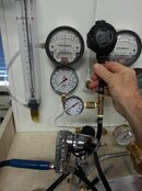
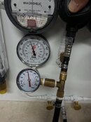
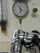
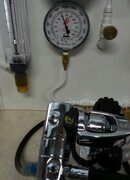
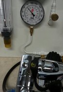
Here's a Mk5 on a test stand with an unbalanced second stage attached.
20130818_090010.jpgThe larger IP gauge below the Magnehelic is attached to an LP port. But I added a second IP gauge on a T-fitting just below the second stage. The intent was to see if "where the IP gauge was located" (in the second case, OUTSIDE the LP chamber of the Mk 5 and closer to the breathing point) would affect the measured dynamic IP. The hope was that the IP would drop less in the gauge right next to the 2nd, because there wasn't whatever venturi effect might be going on in the LP chamber of the Mk 5, and we were sampling nearer where the diver was breathing. Well, here were the results.
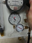
Here's the static IP:
20130818_090245.jpg IP of 132 on both gauges at 400psi supply pressure.
And here's the dynamic measurement at high flow (i.e., I hit the purge button)!
20130818_090204.jpgIP drops to 105 in the turret of the Mk 5, and 75 in the T-fitting!!!

Well, of course in retrospect, it all makes sense. Whether or not there's a venturi effect going on in the turret of the Mk 5, there CERTAINLY is a venturi in the T-fitting. It's a classic fitting in that regard: the sampling port T's off a narrowed waist inside the brass fitting, so of course pressure will drop as the gas races by. Dr. Bernouilli says so.

So that's where it all started.
Luis, sounds like you might be able to give us the answers to our first question:
1) Can you reliably even measure dynamic IP with a gauge on a hose attached to the turret? Or do you need special equipment that eliminates the possibility of a venturi effect somewhere in the measuring system?

But what we should have done was to test the original "observation", that Mk 5's had less of a dynamic IP drop than the Mk 10. As I said before, that was our original mistake before I set off on a tangent about venturi effects and measuring dynamic IP.
Intuitively, it just didn't make sense. It seemed intuitively that if a reg can provide better flow, there should be less of a drop in the supply pressure to the second stage when it's flowing. And yet...there's that Bernouilli thing.

So here are the results when I finally compared the Mk 5 to the Mk 10:
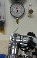
Mk 5 on the bench at 400 psi:
Static 132 psi; Purge IP 98 psi; Change in IP: 34 psi
20130818_094435-1.jpg20130818_094441-1.jpg
Here's the Mk 10 on the bench, also at 400 psi supply pressure:
Static IP 126psi; Purge IP 104 psi; Change: 22 psi.
20130818_094904-1 (1).jpg20130818_094916-1.jpg
Yeah, I know. I should have done it on the flowmeter, so the purge flows were comparable, but I'll have to set that up later to confirm.
If these results are equivalent, then the original comment made by someone else was just a rumor repeated so often it became "true." The Mk5 IP doesn't drop less than the better performing Mk10, it drops more. But in any case, the last question still stands:

When the dynamic IP drops, does that contribute significantly to why an unbalanced second stage breathes harder with "cheaper" first stage regulators, because it's seeing a lower supply pressure in mid-breath? Or is it the poorer flow provided by a bad first stage? Which is the governing factor?

Me, I think it's all the IP drop, because the flow at the second (not what the first is capable of) is directly related to input pressure.
 
Last edited:
Maybe you could also have a look at the difference (if any) that a 1/2" port and the associated larger diameter hose makes to flow rates and IP drop? These were touted as increasing flow to the second stage and were a selling point on top of the line Aqualung and Mares regs (among others), but went out of favor sometime in the 90's because it was thought that they made no real difference and the DIR long hose users wanted standardized ports (what ever happened to the DIR mob?).

I believe that question has been answered. The Work of Breathing guys can create a situation at depth with thick air and huge flows where a 1/2" vs 3/8" port makes a difference. But for most everything else, it's not noticeable. The first stage is capable of providing more air than most everyone else needs (except the US Navy).

You can also take the Poseidon/Cyklon route and build a reg with a much higher IP. Great flow at depth.

As far as the hose diameter and length goes, there are DIR folks who say you can feel a difference, and physics tells us that there will be more resistance in the longer hose. But again, while I haven't measured it yet, it's probably only significant at high workload/high flow rates and low IP's, as might be set for ice diving. That might be a place for shorter hoses, but then there's the cave thing. But Scubapro agrees with you on hose diameter and resistance. They've marketed the Superflo hose, I think it's called. Once again, the diffs are shown mostly in the lab, except for the guys that can feel the difference.
 
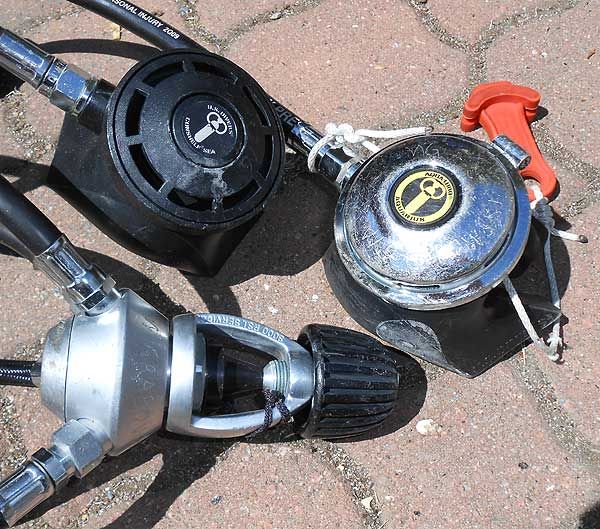
Well this thread has legs and has gone in an interesting direction. I'm not sure I have much to contribute but, for the sake of getting it into my subscribed list, here's a pic of my regulators:


My late wife won the USD Royal Aqualung regulator, a tank and BC in 1982 at the grand opening of a dive shop in North Carolina (Waterworld, I believe, near Durham). It breathed nice but few shops could tune it so tended to free flow and was relegated to being my backup setup for many years. Eventually USD issued a recall on the second stage and replaced it with the Conshelf SEA shown (USD wanted $50 for this, but Wallins swapped it for free). It has been my primary setup ever since.

I recently bought some high pressure steel tanks and was concerned about the 3000 psi stamp on the yoke, but this thread has put my mind at ease.
 
Last edited:
The Royal was an interesting 2nd stage.
It was slightly bigger than their standard 2nd stage, had an additional adjustable side exhaust and was USD's only attempt at a balanced 2nd before they adopted the current Apeks design.
 
rsingler,

Thanks for the information and photos of your setup. That tells me a lot.

I am an industrial hygienist by training, and have worked in this field and safety for about 36 years. I am not an engineer like Luis, but my son is so I can bounce things off him. I also have been diving since 1959, and so have seen my share of regulators, and my collection is a good representation of older regulators. So I have some insights others may not have.

I'd like you to go back to your bench, and do something with your regulators and take another set of readings. Switch the primary LP line from the side to the top of the regulator. A stamped, mitered 90 degree turn in an air flow pattern results in a loss coefficient of 2.50 (Figure 9-e, date 1-07, page 9.50 of the ACGIH Signature Publication Industrial Ventilation, A Manual of Recommended Practice for Design, 26th Edition--this is the "Bible" of industrial ventilation). By simply mounting the Mk 5 on top, and the Mk 10 on the side, you may see the results people are talking about for better flow. There is a lot of turbulence set up when you make that 90 degree turn, and this will adversely affect the flow rates you see. Industrial Ventilation says that this condition should be avoided in designing ventilation systems, and it applies here too as Scubapro found out in the 1970s U.S. Navy EDU tests.

The graph I put up comes from the publication, A.I.R. I Air Inhalation Regulator Second Stage, Addendum to TECHNICAL MANUAL for SCUBAPRO REGULATORS (Cat. 45-101-187), with a date of 1979. It came with my A.I.R. I second stage, which I still have and still dive. The top graph states:
TEST DEPTH AS INDICATED Ft/Mt
SUPPLY PRESSURE 300 PSI/ATM
SECONDARY PRESSURE 135 PSI/ATM
TIDAL VOLUME 2 liters
BREATHING RATE 20 BPM
For the bottom graph:
TEST DEPTH AS INDICATED Ft/Mt
SUPPLY PRESSURE 2000 PSI/ATM
SECONDARY PRESSURE 135 PSI/ATM
TIDAL VOLUME 2 liters
BREATHING RATE 20 BPM
This was done by ScubaPro R&D in 1979, using Model 12-126-000, Serial 17779083.

In their "Installation" portion of this publication, Scubapro makes this statement:

The hose may be connected to either the right-hand or the left-hand port of the regulator. The unused port must, of course, be capped with the provided plug. Commercial or advanced divers requiring improved flow performance at depth can connect the A.I.R. I Second Stage to the first stage with two hoses, one over each shoulder. Maximum flow performance and safety can be achieved by attaching the A.I.R. I Second Stage to two independent first stages which, in turn, are mounted on separate high-pressure cylinders.

You talk about the long hoses of the DIR divers as having "increased resistance." I'll let Luis comment on that, but the resistance would be due to turbulence, and this may be overcome by the increase in volume of air available. What Luis is saying about increases drop in IP due to a larger diameter opening makes sense if the hose length and volume is constant in the comparison. But if the volume is increased, the "pool" of air would be increased and I think you'll see that the IP drop is not as great. The same goes for Scuabpro's statement about using two regulators feeding the A.I.R. I Second Stage; not only is the volume increased (doubled), but also the diameter of orifices into the second stage is effectively doubled. I think this is the basis for Scubapro's statement about improved flow rates at depth. The denser gas has much more volume and area to go through.

Concerning the U.S. Navy being the ones needing the increased flow, that simply is not true. An overweighted diver, in poor condition in current in a sport diving situation will have very high respiratory demand. I've seen fatalities from this situation. By the way, breathing at 50 breaths per minute (BPM) is hyperventilation, and actually reduces oxygenation of the blood. This is because this rate dictates a very shallow breath, and you won't get the exchange needed. The use of 20 breaths per minute by Scubapro is based upon research results for active divers, and is more realistic.

SeaRat
 
Last edited:

Back
Top Bottom