

You are using an out of date browser. It may not display this or other websites correctly.
You should upgrade or use an alternative browser.
You should upgrade or use an alternative browser.
$500 Compressor Kit
- Thread starter joebob24
- Start date
Please register or login

Welcome to ScubaBoard, the world's largest scuba diving community. Registration is not required to read the forums, but we encourage you to join. Joining has its benefits and enables you to participate in the discussions.
Benefits of registering include
- Ability to post and comment on topics and discussions.
- A Free photo gallery to share your dive photos with the world.
- You can make this box go away
Reading the head temp won't tell you much, read the temp of the discharge gas.
The closer you can get to ambient in the Inlet side, the better.
You probably want to run it very slow. this looks like 2 stages? The only way to have that work is at low speeds so I would be in no hurry to speed anything up. What are the ring seals made of?
The closer you can get to ambient in the Inlet side, the better.
You probably want to run it very slow. this looks like 2 stages? The only way to have that work is at low speeds so I would be in no hurry to speed anything up. What are the ring seals made of?
Gone for diving
Contributor
These cooling sleeve. How does it cool.
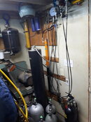
Last picture looks like you are using water? (Like the chinese compressor do.)
If your 155* on the head, the air temp probably will be higher,
You also need a way to cool and drain water between the stages.
If you are water cooling.
This or something similar may be a good option for the first stage, and you'll get good water drop out,
What would you recommend for a discharge temperature limit measured on the line as close to the head as possible?Reading the head temp won't tell you much, read the temp of the discharge gas.
The closer you can get to ambient in the Inlet side, the better.
You probably want to run it very slow. this looks like 2 stages? The only way to have that work is at low speeds so I would be in no hurry to speed anything up. What are the ring seals made of?
It is 2 stages, but it has an inlet pressure of around 115psi on the first stage, so it is closer to a 3 stage as far as heat generation.
There are no rings in the second stage and the first stage has glass filled PTFE seals right now. I don't have very high confidence in the seals, but they were only $3, so I thought it would give them a try. I am hoping they last until the 100 hour service at least. It is at 7 hours of run time right now.
Attachments
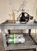
The cooling sleeves are press fit around the top of the cylinders and port compressed air around the cylinder and up through the head. They aren't a good long term solution, but they work well for this stage of prototyping, where I am focusing on the piston and valves. I would estimate that I am blowing about 15 SCFM through it to keep it cool right now. Not something the average person is going to be OK with.These cooling sleeve. How does it cool.
Last picture looks like you are using water? (Like the chinese compressor do.)
If your 155* on the head, the air temp probably will be higher,
You also need a way to cool and drain water between the stages.
If you are water cooling.
This or something similar may be a good option for the first stage, and you'll get good water drop out,
The inlet air I am using is already very dry. I am only getting a few drops of water in the separator after running for 2 hours. These are problems I will work on later in the process if I can get this part to work. I am a little surprised I haven't broken anything yet.
Gone for diving
Contributor
The inlet air I am using is already very dry. I am only getting a few drops of water in the separator after running for 2 hours
It is 2 stages, but it has an inlet pressure of around 115psi on the first stage, so it is closer to a 3 stage as far as heat generation.
Wait. Are you using a shop air supply input, that's acting as the first stage?
If yes,
this is making way more sense...
I do something similar.
Shop air 150-175psi into a large dessicate filter, into a large hydraulic accumulator into low bank cylinders, Then high bank or scuba tanks.
Attachments
I sent files out to a shop for some rough pricing. Looks like the cost of the parts would be around $550 if 10-15 people got together and sent the parts out to a shop together. There are a few things in the design that I think would need to change for the average person to be able to assemble it though. Inflation has been rough on the pricing. Some of the purchased parts have increased in price significantly since I started this. Machined parts are up almost 50% as well.

The second column is the approximate of how much I have spent to put the prototype together. I have machined all of the parts shown in blue myself. It does not include things like oil, motor, or filtration system. So far it has only put out about $60 worth or air, so I have a way to go to recoup my cost. Although, I can't get cave fills where I am, so those are close to priceless.
My plan going forward is to keep running it until something breaks. At some point, I will put together a CAD package and parts list, so anyone with the required skills can build one or make improvements as desired. I do not plan on supplying any parts myself.
So, it is 3 stages then, that's good.What would you recommend for a discharge temperature limit measured on the line as close to the head as possible?
It is 2 stages, but it has an inlet pressure of around 115psi on the first stage, so it is closer to a 3 stage as far as heat generation.
There are no rings in the second stage and the first stage has glass filled PTFE seals right now. I don't have very high confidence in the seals, but they were only $3, so I thought it would give them a try. I am hoping they last until the 100 hour service at least. It is at 7 hours of run time right now.
You say no rings on the final stage, is it oil lubricated?
The closer you can cool it to ambient between stages , the better.
What interstage pressures are you running? (Do you have uniform CRs)
My advice is to keep it slow for now and get the interstage cooling worked out. The vast majority of heat is rejected from the there and not the cylinders.
This is a very cool project, keep it up!
It is oil lubricated. I am feeding a small quantity of oil through with the air and it also gets some splash lubrication from below. Some of the commercial compressors use a similar design, but I think most of them use the piston inverted with the backside bathed in oil. It is one of the areas I am keeping a pretty close eye on.You say no rings on the final stage, is it oil lubricated?
The inlet pressure is around 100 psi, second stage brings it to around 700 psi. The final stage CR varies depending on output pressure, but runs closer to 5 or 6. I would have liked to use a slightly smaller second stage and a larger final stage, but I am using off the shelf components, so I was not able to match them perfectly.What interstage pressures are you running? (Do you have uniform CRs)
I ordered some longer tubing for interstage cooling, so when that gets here I will see if I can find a routing plan that keeps in in the moving air and not rattling all over the place.
Similar threads
- Replies
- 3
- Views
- 628
- Replies
- 5
- Views
- 891
- Replies
- 15
- Views
- 1,428
- Replies
- 1
- Views
- 432
