OP
Very cool Z ")
I think that it's good light, and especially so, considering the cost
.. I updated the photo
I think that it's good light, and especially so, considering the cost
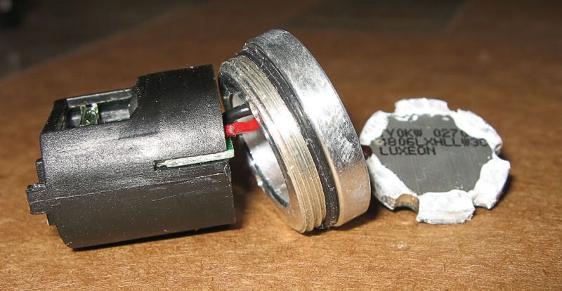
After looking closely at it, it looks to be seperate piece and glued into the body with some black siliconeThanks for the pictures D_B. I still haven't gotten the head off my light - sigh. I'm experimenting with a variety of "liquid wrench" type products, clamps and wrenches. So it's fun to see what I'm up against.
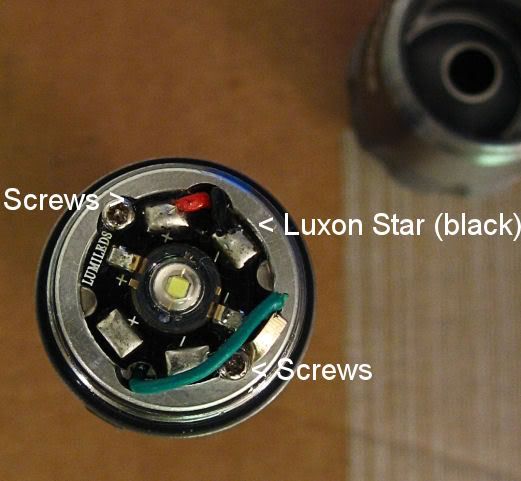
Is the metal "seat" for the Lumiled star part of the body?
Henrik
.. I updated the photo
 , coz I think 700ma is good enough with a longer run time and not to push the LED too hot.