A repository of 3D print STL sources

Please register or login

Welcome to ScubaBoard, the world's largest scuba diving community. Registration is not required to read the forums, but we encourage you to join. Joining has its benefits and enables you to participate in the discussions.

Benefits of registering include

  • Ability to post and comment on topics and discussions.
  • A Free photo gallery to share your dive photos with the world.
  • You can make this box go away

Joining is quick and easy. Log in or Register now!

Well I think it's awesome. If Vance can use whiffle balls I'm pretty sure just about anything would help in disrupting the flow enough to get a mix.... and honestly who cares. I get that there may be more efficient designs, but if I tie 3-4 of these together in an 18"-24" housing I'm pretty sure it'll work.

You might be right, a more efficient design could be shorter, but it also costs a lot more money. I don't think most people care about short....
 
Would it be a good idea to make a mirror image of half the sections to get better mixing in which case just push together would be easier.

Planning on mirroring, I'll do 3 STL's.... a push together that can be mirrored in the slicer, and part a (right handed) and part b (left handed) threaded

Just my opinion, but I don't think that design will work as well as you may like it to. I've seen quite a few designs along this path and some of the better ones have designs that split the airflow paths, and your design seems to be 2 opposing spirals without any path splits. Just doesn't seem like it would make enough turbulence to really get the 2 (or more) gasses to mix.

I very much appreciate constructive criticism! I agree, and plan on doing mirrored sections, alternating.

Respectfully,

James
 
Standard disclaimer: This has zero testing or math applied... not intended for actual use, purely a thought exercise. Print at own risk.

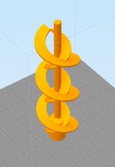
Friction fit version (.5mm tolerance) 50 mm diameter, 150 mm working length (center post goes to 170 mm for 20 mm overlap in the base of next segment). Recommend mirroring in slicer to do alternating directions.

Respectfully,

James
 

Attachments

Thankyou for your efforts in this. Much appreciated.
 
Standard disclaimer: This has zero testing or math applied... not intended for actual use, purely a thought exercise. Print at own risk.

Friction fit version (.5mm tolerance) 50 mm diameter, 150 mm working length (center post goes to 170 mm for 20 mm overlap in the base of next segment). Recommend mirroring in slicer to do alternating directions.

Respectfully,

James

Looks amazing. I can wait for the others to come out. I'd like to line them up and see what'll work. I really appreciate your efforts.

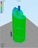
My splicer say's $1.27 @ 50% infill and 20% support infill;
 

Attachments

  • Capture.JPG
    Capture.JPG
    43.7 KB · Views: 71
  • Capture2.JPG
    Capture2.JPG
    63.3 KB · Views: 70
Looks amazing. I can wait for the others to come out. I'd like to line them up and see what'll work. I really appreciate your efforts.

My splicer say's $1.27 @ 50% infill and 20% support infill;
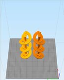
Just a warning, the vanes are only 2mm thick.... I don't know how well the supports are going to play out. This was a quick and dirty design with no real effort to optimize for print-ability.
 
Just a warning, the vanes are only 2mm thick.... I don't know how well the supports are going to play out. This was a quick and dirty design with no real effort to optimize for print-ability.

I guess I'll let you knowo_O:)

Edit: they look great
 

Attachments

  • Capture3.JPG
    Capture3.JPG
    49.3 KB · Views: 71
  • Capture4.JPG
    Capture4.JPG
    52.5 KB · Views: 71
I guess I really don't need supports with it spiraling up, yeah?

Edit: printing both without supports will cost.....exactly $0.99
 
  • Like
Reactions: OTF
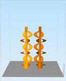
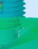
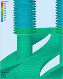
I'm having an issue after slicing where there's "air gaps" in the model.

Any ideas?
 

Attachments

  • Capture5.JPG
    Capture5.JPG
    82.8 KB · Views: 71
  • Capture6.JPG
    Capture6.JPG
    80.6 KB · Views: 79
Back
Top Bottom