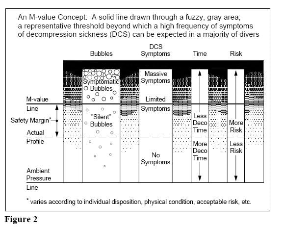
I was going to post something similar but you beat me to it. Baker didn't want to just make the dive more conservative at surfacing which could be done with just GFHi. He wanted to provide an additional setting (GFLo) in order to adjust the slope of the TC m-value limit throughout the entire dive. This gets implemented in DC's by letting GFLo determine the depth of the first stop. The first stop and the surface provide the terminal points in the profile which gives the slope of the line defined by tissue pressure and depth (or the pressure at depth). You can see the relationship between GFLo, GFHi, and current GF in the graph below.
The number of additional stops needed to arrive at the surface is divided into the difference in GF's. This value, the GF increment, is added to GFLo and then to each shallower stop until the surface is reached so that current GF equals GFHi.
For example, if GFLo/GFHi is equal to 60/80 and the first stop is calculated to be 40 ft. Using 10 ft between stops gives a GF increment value of (80 - 60) / 4 = 5. The ascent profile then looks like this:
Stop depth: 40, 30, 20, 10, 0.
Current GF: 60, 65, 70, 75, 80.
View attachment 765063