Which thread gauge to choose?

Please register or login

Welcome to ScubaBoard, the world's largest scuba diving community. Registration is not required to read the forums, but we encourage you to join. Joining has its benefits and enables you to participate in the discussions.

Benefits of registering include

  • Ability to post and comment on topics and discussions.
  • A Free photo gallery to share your dive photos with the world.
  • You can make this box go away

Joining is quick and easy. Log in or Register now!

pisauron

Contributor
Messages
195
Reaction score
85
Location
israel
Hi,

I am looking to buy thread gauges (go no-go) to improve my accuracy and quality of visual inspection of threads.

I stumbled on 3 types of ring gauges (to test the valve threads):
1. Smooth ring gauge
2. "Cracked" ring gauge
3. Regular ring gauge

(I attached sample photos)

What are the different uses of them? Which ones do I need? Maybe I need all of them?


Thanks,
 

Attachments

  • Captur2e.JPG
    Captur2e.JPG
    6.5 KB · Views: 21
  • thread-ring-gages-metric-set.jpg
    thread-ring-gages-metric-set.jpg
    15.7 KB · Views: 23
  • Y2658485-01.jpg
    Y2658485-01.jpg
    71.9 KB · Views: 20
Smooth ring gauges (Picture 1) are fairly useless in my opinion. They are used to check the overall diameter of a thread. Honestly, this can be somewhat achieved with a caliper, although I do admit its more accurate with a smooth ring gauge.

I'm not a fan of segmented ring gauges (Picture 2). Their key advantage, that they can be adjusted, is in my view their biggest weakness. If you drop one on a hard floor, there is a very real possibility it goes out of spec. Short of sending it to a calibration facility, there is no way you get it back up to speed.

What you want are the regular gauges (Picture 3). Depending on what you are checking you need the following.

For M25x2 threads:
  • M25x2 6g Go & No-Go ring gauge
  • M25x2 6h Go & No-Go plug gauge
For ¾"-14 NPSM threads:
  • ¾"-14 NPSM Go & No-Go ring gauge class 2A
  • ¾"-14 NPSM Go & No-Go plug gauge class 2B
External threads are either in class 6g (Europe) or 2A (U.S.) Internal threads are either in class 6h (Europe) or 2B (U.S.). The plug gauges are often combined into one piece, with one gauge at each end of the plug. That means you usually have three pieces of equipment to check the threads of the cylinder valve and cylinder.

Thank you very much for the explanation. I now understand the difference better.

I own internal threads, they are very useful.

I have some valves in which the thread diameter seems a bit short or pressed down from long use. For these valves I can use the smooth/caliper option? I'll start with the caliper I guess - so what is the overall diameter to look for?

And I will purchase the regular gauges for now.

Thank you very much!
are you using m25 or 3/4 valves?

M25x2 is.... drum roll please 25mm external dimension. The minor dimension is 22.92mm
3/4"-14 NPS is 1.034 inches in the major dimension and 1.024 inches in the minor dimension
 
are you using m25 or 3/4 valves?

M25x2 is.... drum roll please 25mm external dimension. The minor dimension is 22.92mm
3/4"-14 NPS is 1.034 inches in the major dimension and 1.024 inches in the minor dimension

We use both here. Aluminum usually 3/4 and steel m25. Depends if they from Europe or USA.

The minor dimension is the "female" on cylinder side?
 
We use both here. Aluminum usually 3/4 and steel m25. Depends if they from Europe or USA.

The minor dimension is the "female" on cylinder side?
The minor dimension on the male part is the "valleys"
The minor dimension on the female part is the "peaks"
 
the peaks of the female part have to fit into the valleys of the male side afterall :)

There are some small tolerances around these dimensions

That's not the version my mom told me...
 
[...]I have some valves in which the thread diameter seems a bit short or pressed down from long use. For these valves I can use the smooth/caliper option? I'll start with the caliper I guess - so what is the overall diameter to look for?
I'm not sure I understand you correctly. If you mean that the diameter of the threads seems less than it should be, for example from worn threads, the valve/cylinder must be scrapped.
A No-go-gauge, is not supposed to go onto the workpiece. The only test that the No-go-gauge performs is that the effective diameter of the thread is not too large or small, depending on whether we are testing internal or external threads. Think of it as testing if the thread has not been “worn down” or the crest has gotten "flattened-out".

Going strictly by the book, a No-go-gauge really is not supposed to go onto the threads at all, not even a tiny bit. But because that is rather a hard bar to clear, exceptions have been made in the past. Luxfer did issue an advisory in the 1980s with regards to their aluminium cylinders with a G ¾” thread. They determined that for a cylinder valve with eleven threads, the G¾” thread could allow up to four turns on a No-go-gauge and still provide ample strength to withstand the forces.
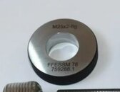
It is important to understand that this is the total turns of the No-go-gauge combined! You have to count the turns of the No-go-gauge on the cylinder valve as well as the cylinder itself and add the two up. If they exceed four turns together, the connection is not deemed safe anymore. For cylinder valves with less than eleven threads, the maximum allowable tolerance was set to two No-go-gauge turns combined. While the G¾” thread is not in use anymore, today's ubiquitous M25x2 and ¾”–14 NPSM threads are fairly similar to that, so that the results transfer reasonably well.
In practice it is a dicey subject, especially when considering that steel and aluminium have vastly different sheer rates for their threads.

Be cautious with the No-go gauge, as it might give you a false sense of security. If the first thread is within specifications, the gauge will not be able to screw on, which is a pass criteria. However, all subsequent threads may as well be completely destroyed or absent and this test still passes. Visual inspection of the threads is imperative for this very reason.

A caliper is not a sufficient tool for thread identification or inspection of threads. You can't possibly measure the fine tolerance required accurately. To drive the point home, think about two threads, both of which have been on SCUBA cylinders or are still in use:
ThreadMaximum Major Male (mm)Minimum Major Male (mm)Maximum Minor Female (mm)Minimum Minor Female (mm)
¾"-14 NPSM26.2626.0124.6424.33
G¾" BSP26.4426.1624.6624.66
M25x2 6g / 6h24.9624.6823.2122.84

The ¾"-14 NPSM and G¾" BSP threads are very close to each other, partly overlapping in sizes. To make matters worse, they differ in flank angles. A caliper can never distinguish between the two flank angles. A thread gauge however will do so easily. The ¾"-14 NPSM has a 60° flank angle, while the G¾" BSP has a 55° Whitworth flank angle.
Without a thread gauge, you will easily mix the two thread types up, creating a combination that is bound to separate violently under pressure.

The measurements of the threads you are likely going to work with are easily obtainable in engineering handbooks, or even the internet. 
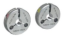
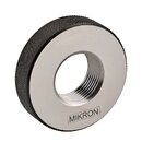
EngineersEdge is a great resource for example. However, I want to stress again, that using a caliper is not a sufficient tool to check threads, you are virtually checking nothing. At the very best, it gives you a false sense of security, at worst you mix up threads. To identify and check threads, thread gauges are the way to go, combined with a thorough visual inspection of the threads.
 

Back
Top Bottom