Split Fin Physics

Please register or login

Welcome to ScubaBoard, the world's largest scuba diving community. Registration is not required to read the forums, but we encourage you to join. Joining has its benefits and enables you to participate in the discussions.

Benefits of registering include

  • Ability to post and comment on topics and discussions.
  • A Free photo gallery to share your dive photos with the world.
  • You can make this box go away

Joining is quick and easy. Log in or Register now!

Second- the number and location of the vortex generators was tuned, not by Force Fin, but by scientific study. This can be easily seen on the Excellerating Force Fin, as the marine engineering lab worked out those locations are the optimum locations. In fact- Bob Evans will recount the story of the lab calling him and asking him, "do you want functional or pretty?" , in the end they choose function and there are only about 10 total on the fin. The Extra Force went through the same process, it started with about 4 times as many as it has now, but the lab informed him that they were overkill and fewer would actually perform better.

VG's on aircraft work by adding energy to the local airflow which makes the airfoil aft of the VG more effective. The added energy from the multiple vorticies comes at a cost and that is additional airframe drag.

I'm not aware of any aircraft originally designed with VG's. Typically their need shows up in wind tunnel or flight testing.

So it is little wonder that the "marine engineering lab" reduced the VG count from near 40 to about 10. My guess had they reduced it to zero, the fins would be even more efficient.

Winglets on the other hand reduce or eliminate the large vortex coming off each wingtip caused by the mixing of high pressure air on the bottom of the wing with low pressure air on the top of the wing. The winglets act as a fences or barriers.

IMHO, if a winglet were to be effective on a fin, the fence would need to run nearly the entire length of the fin on both sides.
 
VG's on aircraft work by adding energy to the local airflow which makes the airfoil aft of the VG more effective. The added energy from the multiple vorticies comes at a cost and that is additional airframe drag.

The end goal of vortex generators on aircraft wings is the keep the flow attached longer (in particular over control surfaces). Yes, you may have higher localized drag in the turbulent regions, but at the same time you'll have less form drag since you'll be creating a smaller wake.


Winglets on the other hand reduce or eliminate the large vortex coming off each wingtip

I don't think they reduce or eliminate them so much as prevent them from affecting the freestream flow.

The mechanism by which tip vorticity induces drag is by effectively changing the freestream direction to something slightly negative (relative to the wing section). That tips the lift vector from vertical to up-and-back. That back component of the force is (induced) drag. Here's a crude picture I made with powerpoint to illustrate.

induced_drag.png


With that in mind, I'm not sure endplates on fins would necessarily decrease drag in the same way they do on an airplane wing since the flow direction and resulting effects are completely different.

They may however serve to channel more flow in the correct direction, and thus reduce energy loss.
 
Ironically, my typical speed happens to be right smack in the middle of the testing speeds used for the Buffalo study (around 1.5 mph).

My average speed is less than that. If I want to go fast I bring an actual propeller :D

n881640654_5842587_6066.jpg
 
Blackwood,

It takes energy to create a vortex whether in air or water!

How do you get downwash ahead of a wing, that is undisturbed air?
 
Blackwood,

It takes energy to create a vortex whether in air or water!

How do you get downwash ahead of a wing, that is undisturbed air?

For one, it doesn't have to be ahead of the wing. For two, considering incompressible flow, perturbations propagate much faster than the motion of the airplane.

I'm not a practicing aerodynamicist even though that was my major concentration, but I do recall seeing tip-induced downwash in a wind-tunnel when running a finite wing versus and infinite wing (i.e. one that spanned the entire width of the test section) as well as in CFD simulations.

This is WAY off topic, but this is a super cool photo that the conversation made me think of: wing tip vorticies from a C-17 (an airplane with huge winglets, FWIW): http://upload.wikimedia.org/wikipedia/commons/3/37/C17-Vortex.JPG
 
F

Note: I find that split fins simplify my choices when pairing up with insta-buddies on dive boats.

I am new to both diving and the boards...but by this inference I would assume this to mean you dismissively "write off" anyone with split fins.

If that is the case, well that is just sad. Especially since I know of several DM's, divers, and even a shop owner or two with decades of diving experience and knowledge who use split-fins.
 
The physicist in me begs to comment, but I'll be very brief. The only way to move forward is to push back on something. All fins move you forward by pushing water behind you. Split fins just do it in a different way that causes a lot of turbulence. Forming turbulence or a vortex is a sign on inefficiency. Some of the energy in moving the fin is ending up is water spinning around in eddies, and ultimately in a very slight heating of the water. All fins are going to have some vortices off the tips and controlling these could make a fin slightly more efficient, but intentionally generating more can be counter-productive. Clearly split fins move people through the water, but not because of lift or vorticies.

As an aside, I'd like to mention that the Bernoulli effect has relatively small affect on airplane wings. As with fins, airplane wings work by pushing air in a direction opposite the direction they want to move. In this case I mean airplane wings redirect air down so that they can move up. Motion forward is what is driving the air past the wing, allowing the wing to direct it down. For example, a good friend of mine at Stanford discusses airplane wings here:

Lift, James Glownia, Stanford University
 
M Bipartitus: Your friends work is very interesting and informative. I do like that the serious pro's are adding to the discussion. Hope we see more.
 
You might be onto something there.
One way to possibly find out would be to inject an ink trail into the oncoming water flow of the fin to visually see exactly what happens.
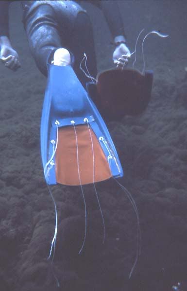
You mean like this:
VikingMod-1.jpg

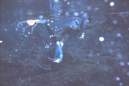
This is an AMF Voit Viking V66 that I modified in 1970 to show the concept of the scoop fin. Here's another view:
VikingMod-2.jpg

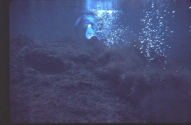
Here you can see the water flowing by the strings. Basically the water flows; more on the physics a bit later in this post. Here is a photo which shows the result of the moving water:
ScoopEffect-1.jpg

Basically, many of you have the physics wrong, in my opinion. The Physicist above, M_Bipartitus, mentioned that you only get movement by pushing against something. The part that is wrong has to do with the "flying" and "wing" concepts, as those apply to air and not to water. The reason they don't apply to water is that water is incompressible, and therefore there is no possibility of a "low pressure" area above the wing.

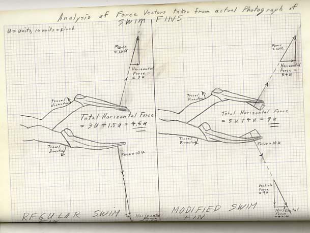
The problem with most blade fins is that there is a dead area at the center of the blade which doesn't push against the water. I did this vector analysis, based upon the one done by Fred Roberts in his book Basic Scuba many years ago (which is why it is in pencil and scanned).
FinVectorAnalysis.jpg

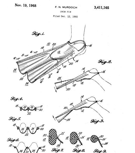
What the scoop membrane does is to provide a larger surface area to the water, and a flow that is at a higher angle to the fin blade itself. I have been using variations on this design for over thirty years, and it was patented by a guy named Murdock years ago:
MurdockPatent.jpg


I will give more information, and my own thoughts on both split fins and others, later. This is enough for one post though.

SeaRat
 
Last edited:
You mean like this:
VikingMod-1.jpg

This is an AMF Voit Viking V66 that I modified in 1970 to show the concept of the scoop fin. Here's another view:
VikingMod-2.jpg

Here you can see the water flowing by the strings. Basically the water flows; more on the physics a bit later in this post. Here is a photo which shows the result of the moving water:
ScoopEffect-1.jpg

Basically, many of you have the physics wrong, in my opinion. The Physicist above mentioned that you only get movement by pushing against something. The part that is wrong has to do with the "flying" and "wing" concepts, as those apply to air and not to water. The reason they don't apply to water is that water is incompressible, and therefore there is no possibility of a "low pressure" area above the wing.

The problem with most blade fins is that there is a dead area at the center of the blade which doesn't push against the water. I did this vector analysis, based upon the one done by Fred Roberts in his book Basic Scuba many years ago (which is why it is in pencil and scanned).
FinVectorAnalysis.jpg

What the scoop membrane does is to provide a larger surface area to the water, and a flow that is at a higher angle to the fin blade itself. I have been using variations on this design for over thirty years, and it was patented by a guy named Murdock years ago:
MurdockPatent.jpg


I will give more information, and my own thoughts on both split fins and others, later. This is enough for one post though.

SeaRat

Now we're getting somewhere.
 

Back
Top Bottom