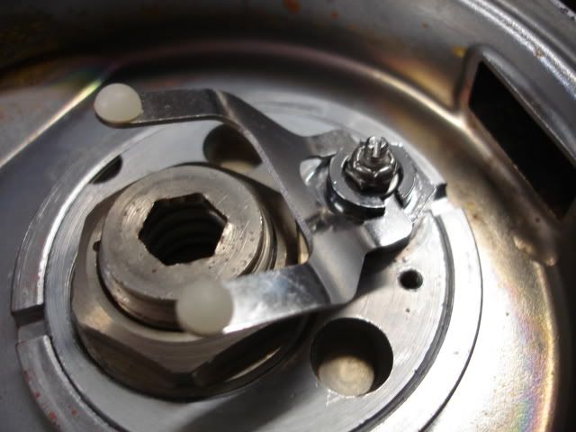
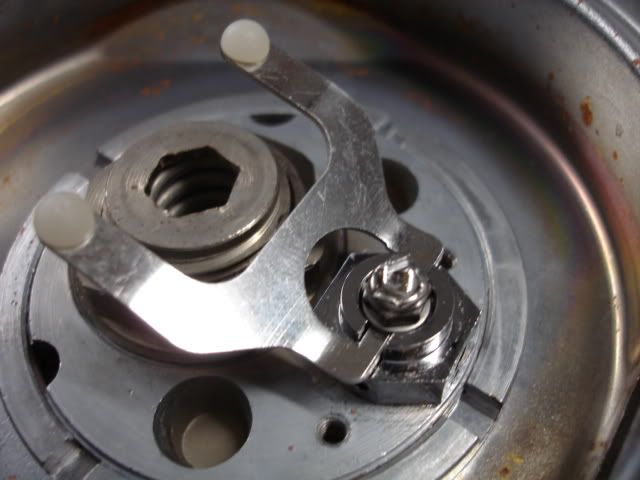
Phoenix HPR Royal second stage

Please register or login

Welcome to ScubaBoard, the world's largest scuba diving community. Registration is not required to read the forums, but we encourage you to join. Joining has its benefits and enables you to participate in the discussions.

Benefits of registering include

  • Ability to post and comment on topics and discussions.
  • A Free photo gallery to share your dive photos with the world.
  • You can make this box go away

Joining is quick and easy. Log in or Register now!

I finally have had a chance to check in on this thread. As usual, Luis you've come up with something that has great potential. I look forward to ordering one of these!
 
Excellent work!
This is a another game changer in the DH world.
Thanks Luis now your 2 for 2.
 
Thanks


The production parts are getting some final QA (quality assurance) checks and some endurance testing (on a inhalation cycling machine).


These are Bryan's pictures:

DSC02207.jpg


DSC02208.jpg


DSC02209.jpg
 
Luis, I'm curious whether there was any advantage to the Trieste second stage lever, which had the backwards double-bend? Does that provide any more mechanical advantage to the lever, or was it simply because they needed to house it in a smaller space with the Trieste?

SeaRat
 
The back bend doesn’t provide any mechanical advantage. The mechanical advantage is calculated by the linear measurements between the points of contact (the points where the forces are applied). They include the fulcrum point, the load point, and the reaction point (they are actually not points, but more like contact lines in this case).

The Trieste has actually lower mechanical advantage due to the limited space. The lever length of the Trieste is fairly short.

It also has a major flaw in the feet area of the lever. There is too much friction and almost some binding in the Trieste. The loads are small enough that it is hard to measure, but it is there.

The lever in the Mentor has a similar shape near the feet of the lever, but it looks to have much better details. Again the actual shape of the lever (between the contact points) is irrelevant. It is just the distance between the points where the forces are applied that makes a difference.

In my design I kept the lever design simple and optimized it to reduce friction and prevent any possibility of binding. Important factors in the design included the material selection (of the bearing/ contact surfaces in particular), the clearances and tolerances, and some of the details.


If you want to learn more about regulator mechanics, I would recommend Pete Wolfinger, Regulator Savvy Book. It is an excellent book about regulator mechanics. The book does have a couple of small mistakes, one in particular about the subject of lever mechanical advantage, but it is just a small detail that is not critical to the explanation. If you buy the book I will be glad to explain the small mistake.
 
Hello Luis,

There are plenty of us who own the book. I'm not an engineer so I'd love to hear the detail you mention and any other elaborations you would like to share.

Thank you,

Couv
 
Hi Couv,

I am going to be traveling for work, but when I get back I will try to explain the discrepancy/ mistake I am referring about. I am even hesitant to call it a mistake because it might have even been an intentional over simplification to keep the explanation simpler. I wouldn’t have an issue with that if it was a different book. This book appears to be written with the intention of being technically accurate.

I will start a new thread on the subject when I get back and I will try to scan the diagram showing the mistake and try to annotate it.

Just as a preview, it is related to the moment arm of a lever. It is related to the direction of the force and the effective moment arm (due to the direction of the force).

In the diagram it is showing the moment arm as the length of the lever, but the force is not perpendicular (at 90 degrees) to that dimension. That is incorrect.

The length of a lever and the effective moment arm are not necessarily the same thing. As an example: I am sure you know that when you use a torque wrench you have to apply the force perpendicular to the wrench (some wrenches even have a swivel at the grip so you can only apply force in the correct direction). If you are using a wrench and apply some of the force in line with the wrench, that portion of the force is not applying any torque.

The same thing applies to all levers. This would be a lot easier to explain if I showed some diagrams. When I get back I will try to start a new thread with this subject… I would like to keep this thread from derailing.
 
Luis, to get the thread back on track, but preserve some information on the second stage lever linkage, I'll explain what I was looking at. I see the photos of the Phoenix HPR Royal second stage, and it appears that the length of the contact surface has been lengthened just a bit from the Royal Aquamaster by USD. This would seem to me to give more lever advantage to the lever you have developed, but I don't see it described above. This contact surface actually is the pivot of the lever, and the far edge the lifting point. It's somewhat like having a longer shovel with the same arm length handle. Is this correct?

SeaRat
 
The lever looks longer than it is due to the angle of the pictures. It is a bit longer than the original RAM lever, but just slightly.

The lever does have a tiny bit more mechanical advantage than the original RAM lever, but not enough to even bother mentioning it. The big difference is not on the lever arm, but on the fulcrum and the point of reacting force (the contact point to lift the seat carrier).

One of the big advantage of this design over the RAM lever (as I mentioned before) is that there are not a lot of parts to align and I reduced the contact point of the lever to very specific locations to avoid binding.

The lever in the RAM often seems to move freely, but it is very prone to have some very small amount of binding forces (friction forces due to misalignments).


John,
The pivot point of a lever is by definition the fulcrum. I am a bit confused by your question… The lever is not pivoting about the contact points with the diaphragm… Is that what you are asking? The use of standard terminology would help. That is one of the reasons why I suggested Pete Wolfinger’s book.


The material selection for the three contact points is related to the magnitude of the force at the contact points and the amount of sliding at that point. The maximum force is at the fulcrum. The force pushing the seat holder up is just a bit less than the fulcrum force.

If you go to VDH in the store area there is a picture showing all the parts. There is a harder stainless steel washer under the lever that acts as the fulcrum bearing. This is an important improvement even over the Trieste lever. The HPR lever does not ride on chrome plated brass. The SS washer lifts the lever so that only the selected points make contact.

The two washers are positioned so that the smooth surfaces are facing the lever.

The force on the diaphragm is a fraction of the seat lifting force (the fraction determined by the mechanical advantage of the lever). The material at the contact points to the diaphragm was selected to work with the sliding motion (reduce friction) with the low predicted force. The diaphragm contact force is about 0.5 Lbs for 1 inWC (this is a function of the diaphragm size).
 
Last edited:
Hi Luis, I was a bit confused, and forgot about the pivot no the Aquamaster; I was mentally thinking of my Trieste II. I don't think the Trieste has as wide a lifting portion as the lever you developed. Looking at the Aquamaster photo (which I did after posting, a case of the fingers getting ahead of the mind ;) ), I see what you are saying. But I think the friction you described with the washer is significant, and I think the washer can move a bit during the lift. 'Sorry for the confusion, but we did get to talking about the new lever.

SeaRat
 

Back
Top Bottom