

You are using an out of date browser. It may not display this or other websites correctly.
You should upgrade or use an alternative browser.
You should upgrade or use an alternative browser.
Need (lots of) help on DIY light
- Thread starter bradsab
- Start date
Please register or login

Welcome to ScubaBoard, the world's largest scuba diving community. Registration is not required to read the forums, but we encourage you to join. Joining has its benefits and enables you to participate in the discussions.
Benefits of registering include
- Ability to post and comment on topics and discussions.
- A Free photo gallery to share your dive photos with the world.
- You can make this box go away
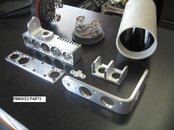
Pressure tested to 350fsw today... two leaks. Bummer. One should be easy to fix, the other will be more of a challenge. If I can get it sealed up, I'm going to try DIY anodizing this weekend. Then all I'll need is the drivers.
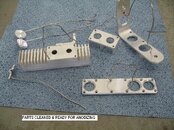
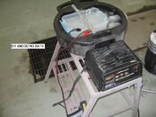
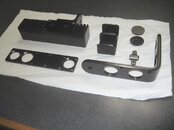
Well, for my first attempt at anodizong, I'm pretty happy with the results. There are a few flaws where either the anodizing or the dye didn't take, maybe I didn't get it cleaned well enough in those spots, or I could've touched the parts before getting them in the dye solution. But overall, it looks good. I tried scratching my test piece and it seems pretty hard, and the parts are all non-conductive. The biggest challenge I had was keeping the anodizing bath at room temp. Even with a single small test piece, it heated up to 90 degrees, so I put the bath tank in a tub of icy water. The first batch stayed under 80, but the second batch had more surface area, and it went over 85. Ideally, it should be kept between 70-75. I found the most useful info here Anodizing Aluminum I bought the black dye and sealer from him, the rest I either had, or bought locally.
I talked to DIYdiver today, said he'd be able to ship the drivers Tuesday. Lord willing, the light will be done for my trip. It's time to be done: my wife now calls this light my mistress
I talked to DIYdiver today, said he'd be able to ship the drivers Tuesday. Lord willing, the light will be done for my trip. It's time to be done: my wife now calls this light my mistress
Attachments
Codiak
Contributor
Well, for my first attempt at anodizong, I'm pretty happy with the results. There are a few flaws where either the anodizing or the dye didn't take, maybe I didn't get it cleaned well enough in those spots, or I could've touched the parts before getting them in the dye solution. But overall, it looks good. I tried scratching my test piece and it seems pretty hard, and the parts are all non-conductive. The biggest challenge I had was keeping the anodizing bath at room temp. Even with a single small test piece, it heated up to 90 degrees, so I put the bath tank in a tub of icy water. The first batch stayed under 80, but the second batch had more surface area, and it went over 85. Ideally, it should be kept between 70-75. I found the most useful info here Anodizing Aluminum I bought the black dye and sealer from him, the rest I either had, or bought locally.
I talked to DIYdiver today, said he'd be able to ship the drivers Tuesday. Lord willing, the light will be done for my trip. It's time to be done: my wife now calls this light my mistress
Anodizing looks nice... so does the fact job!
Looks like DIYdiver is going to be the first to market with the 5 and 10A CC drivers, YEAH!
DIWdiver
Contributor
View attachment IS1006.doc
Hi gang,
I finished the first draft of the data sheet for my driver. I intended to post it on the CPF site, but apparently I'm not allowed to post attachments there.
As this is a rough draft, it will need some work. I'm interested to hear what you can and can't understand, and what's missing.
This is my first attempt at a data sheet, so please be gentle!
The file is a Word format document created in OpenOffice 2.4/Writer.
D
Codiak
Contributor
View attachment 72855
Hi gang,
I finished the first draft of the data sheet for my driver. I intended to post it on the CPF site, but apparently I'm not allowed to post attachments there.
As this is a rough draft, it will need some work. I'm interested to hear what you can and can't understand, and what's missing.
This is my first attempt at a data sheet, so please be gentle!
The file is a Word format document created in OpenOffice 2.4/Writer.
D
Reviewing doc... a suggestion is to public in PDF... it's easy to use a print to pdf like PDFCreator | Get PDFCreator at SourceForge.net
EGad
Contributor
The doc looks pretty good to me. I was able to wrap my head around nearly everything. Looks like this is going to be one of the best drivers out there. I was really not looking forward to running an array of 1400mA drivers. Also, OpenOffice Writer can export directly to pdf. It's on the toolbar right over by the print button.
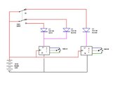
Well, I was only able to wrap my head around about 5% of the doc, which is why you're building and I'm buying . Is the attached wiring diagram still valid? I see in your doc you have L+ & L-, but the diagram routs the + thru the SST-90 before connecting to L+, and L- is not used.
Assuming the diagram is till correct, I plan to use 16 gauge cable from the canister to the head, and the + will connect directly to SW1. The - will split into two 18 gauge and connect to B- on each driver. I'll use 18 gauge from SW1 to the LEDs, and from the LEDs to L+ on each driver. SW2-A&B circuts will be 36 gauge. What do I need for the wires going to B+ on the drivers? Can that be 36 gauge?
. Is the attached wiring diagram still valid? I see in your doc you have L+ & L-, but the diagram routs the + thru the SST-90 before connecting to L+, and L- is not used.Assuming the diagram is till correct, I plan to use 16 gauge cable from the canister to the head, and the + will connect directly to SW1. The - will split into two 18 gauge and connect to B- on each driver. I'll use 18 gauge from SW1 to the LEDs, and from the LEDs to L+ on each driver. SW2-A&B circuts will be 36 gauge. What do I need for the wires going to B+ on the drivers? Can that be 36 gauge?
Attachments
lucca brassi
Contributor
@Bradsab
This circuit is a section from linear power supply's. It will generate a lot of power with big power consumption.
Same thing you can do more accurate and safe with LM337 conected parallel ( look current circuit ( output and GND connected with resitor ) and LMV641 is a 10 MHz, 12V, Low Power Amplifier !
DIWdiver
Contributor
Well, I was only able to wrap my head around about 5% of the doc, which is why you're building and I'm buying
Assuming the diagram is till correct, I plan to use 16 gauge cable from the canister to the head, and the + will connect directly to SW1. The - will split into two 18 gauge and connect to B- on each driver. I'll use 18 gauge from SW1 to the LEDs, and from the LEDs to L+ on each driver. SW2-A&B circuts will be 36 gauge. What do I need for the wires going to B+ on the drivers? Can that be 36 gauge?
Your diagram is correct except that the LEDs connect to L- on the driver. Your wire sizes are fine. L+ is just the same point as B+, I provided two terminals there for applications where it would be convenient.
Please PM me your address so I can ship the drivers.
D
Similar threads
- Replies
- 7
- Views
- 769
- Replies
- 2
- Views
- 86
- Replies
- 4
- Views
- 989
- Replies
- 0
- Views
- 253
