Yes most linear drivers will hold the current constant until the batteries reach some particular voltage, then will start to drop. The driver will always need to have some voltage across it, and mine is designed to keep up to 10A constant current down to 4.0V input, 3.6V output. It would continue to provide output as the voltage drops, down to at least 3.0V. After that I wouldn't be comfortable promising what would happen, but it would probably work down to 2.0-2.5V. At lower power settings, the minimum voltage is a little lower.
D
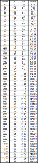
One thing I'm confused about: your driver will put out constant current at whatever amps you make it to be. But regardless of the amp level you choose, it will always have 3.6V output? All the charts I've seen on the SST-90 show higher amps = higher voltage. Looking again at this thread White LED lumen testing - Page 11 - CandlePowerForums (I attached the chart I'm referring to) can you hold the V to 3.6 and push it to 9A and still get 2136 lumens? Or hold 3.6V and drop to 1A and get 307 lumens? If lumen output is totally current driven regardless of voltage, could you make the output a constant 4.0V and raise the driver's efficiency?