My Rix SA-6 Diesel

Please register or login

Welcome to ScubaBoard, the world's largest scuba diving community. Registration is not required to read the forums, but we encourage you to join. Joining has its benefits and enables you to participate in the discussions.

Benefits of registering include

  • Ability to post and comment on topics and discussions.
  • A Free photo gallery to share your dive photos with the world.
  • You can make this box go away

Joining is quick and easy. Log in or Register now!

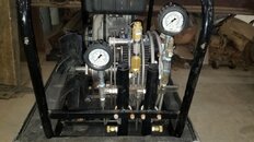
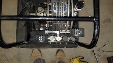
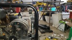
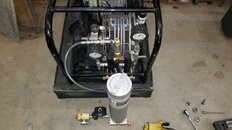
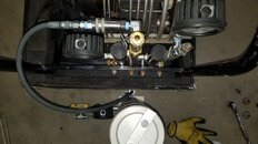
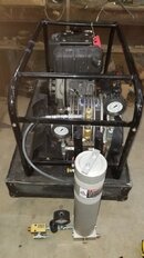
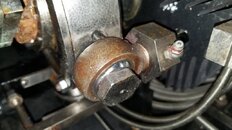
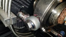
So here are some pictures with the shroud and the belt cover off. Everything moves as it should, blue spring doesn't move at all. Except for some surface rust from sitting really looks in good shape. I need to clean the excess grease off in some spots, but overall I'm pretty excited. Seems like a very well thought out / engineered unit, but also easy to service.

I'm not an expert, but pretty neat layout.

View attachment 629700 View attachment 629701 View attachment 629702 View attachment 629703 View attachment 629704 View attachment 629705 View attachment 629706 View attachment 629707

I think I've seen these compressors some place before only I thought they looked much cleaner. Memory not what it was or everything back then was much cleaner and brighter.


But just a couple of observations before I grab some sleep
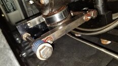
The red coloured grease you can see on those zerk grease nipples and around the second stage rod end bearing looks (from that poor small photo) to be a Lithium base soap type lubricant Its OK but only just and not the correct lubricant for the SA-6 .

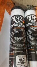
When your ready consider changing to a Polyurea blue colour or color if you prefer lubricant.
Clean all that old stuff up maybe even remove those three 1" AF bolts (60 ft/ibs torque) and clean inside the rod end bearing housing also note the position of the inner ball race, by marking its postion with a black marker pen.

Inspect the inner ball for scuff marks at the back end and when re fitting turn the inner ball using the mark you made earlier say 90 degrees so a "new face" now touches the back end of the bearing housing. This will extend the life of thse rose head or rod end bearings no end. Re grease after 10 hours running there after every 30 hours and clean your grease mess up

In addition while the bolt is out and the inner race is all cleaned up you can assess the wear on the bronze bearing housing with a pair of automotive feeler gauges that is the part that holds the hard chromed inner ball against the hardened steel outer housing. You can do the same thing when its all assembled by pulling and pushing the piston rod back and forth to assess any play or slip, its easier to do before you clart up the bearing housing with new grease.

You can also choose to remove the entire piston rod out if you so want or leave the piston still inside the liner for all stages.

My preference at this stage would be if you remove the pistons on stage one and two only and leave the 3rd stage floating piston alone just remove the 3rd stage rod and rod end assembly Then clean up all the rods ends, and the pistons in 1 and 2

A good trick is to replace the 0 rings only on stage 1 and stage 2 but put back the old compression rings 1 & 2. Its a cheap dirty trick but it extends the spiral compression rings no end up to three times the life expectancy for the sake of a cheap viton oring that on observation you will see is scuffed and worn in two positions on stages 1 and 2

Forget doing this o-ring replacement trick on stage 3 it wont work you will damage the partially worn ring permanantly and never get them back on to the floating piston assembly 3rd stage

IMHO also dont worry to much about using industrial quality Viton 0-rings as you dont need too much the close tolerance Aircraft quality higher priced Mil Spec 0-rings Rix and ourselves use in Europe. Just make sure its Dupont Viton and not some junk from East Far pretending. Iain
 
Again on another photo you can see that Bearing Nut or Lock Nut (part 181-303) has rusted up solid its holding the swash plate bearing onto the crankshaft it does an important job and its rusted solid. Its also cheap to replace and darn impossible if you leave it any longer
Its on the front, fan side of the crankshaft

I would consider replacing it with a new shiny one as they are not expensive SKF N08 from memory and while your at it replace the washer locking devise part SKF W 08 as well.

Again get the proper SKF components and not junk from Ebay You can get them from Rix if you prefer and pay $2 more to keep good engineers in a job. Also dont forget to consider the other one on the other side at the Flywheel end.

Now to get them off remove the fan first or you will snap it and hold the crankshaft with an 18 inch Adjustable Spanner, to be honest I'm just not sure how to interpret that into American I think Crescent Wrench may be the correct interpretation.

Spray WD40 all over the thing add some heat just not with the wifes hairdryer and whack it off with a cold chisel if you can. Fail in this and your in real trouble, get caught using the wifes hairdryer on it and you in even worse.

To fit the new replacements your going to need an SKF N08 Hook spanner again I'm just not sure how to interpret that either, Good news for us lot is we free hire them out with the spares kits I know not much use for you lot. time for sleep. Iain
 
I think I've seen these compressors some place before only I thought they looked much cleaner. Memory not what it was or everything back then was much cleaner and brighter.


But just a couple of observations before I grab some sleep
The red coloured grease you can see on those zerk grease nipples and around the second stage rod end bearing looks (from that poor small photo) to be a Lithium base soap type lubricant Its OK but only just and not the correct lubricant for the SA-6 .

When your ready consider changing to a Polyurea blue colour or color if you prefer lubricant.
Clean all that old stuff up maybe even remove those three 1" AF bolts (60 ft/ibs torque) and clean inside the rod end bearing housing also note the position of the inner ball race, by marking its postion with a black marker pen.

Inspect the inner ball for scuff marks at the back end and when re fitting turn the inner ball using the mark you made earlier say 90 degrees so a "new face" now touches the back end of the bearing housing. This will extend the life of thse rose head or rod end bearings no end. Re grease after 10 hours running there after every 30 hours and clean your grease mess up

In addition while the bolt is out and the inner race is all cleaned up you can assess the wear on the bronze bearing housing with a pair of automotive feeler gauges that is the part that holds the hard chromed inner ball against the hardened steel outer housing. You can do the same thing when its all assembled by pulling and pushing the piston rod back and forth to assess any play or slip, its easier to do before you clart up the bearing housing with new grease.

You can also choose to remove the entire piston rod out if you so want or leave the piston still inside the liner for all stages.

My preference at this stage would be if you remove the pistons on stage one and two only and leave the 3rd stage floating piston alone just remove the 3rd stage rod and rod end assembly Then clean up all the rods ends, and the pistons in 1 and 2

A good trick is to replace the 0 rings only on stage 1 and stage 2 but put back the old compression rings 1 & 2. Its a cheap dirty trick but it extends the spiral compression rings no end up to three times the life expectancy for the sake of a cheap viton oring that on observation you will see is scuffed and worn in two positions on stages 1 and 2

Forget doing this o-ring replacement trick on stage 3 it wont work you will damage the partially worn ring permanantly and never get them back on to the floating piston assembly 3rd stage

IMHO also dont worry to much about using industrial quality Viton 0-rings as you dont need too much the close tolerance Aircraft quality higher priced Mil Spec 0-rings Rix and ourselves use in Europe. Just make sure its Dupont Viton and not some junk from East Far pretending. Iain

Lots of good info, thank you. A lot of what you wrote is in the plans. The right grease has been ordered, with all the holiday delays it says arriving next week. Plan to clean everything up and take a good look at all the bearings and rotate ball if needed.

I believe I was told grease every 50 hours, but I'll happily grease every 30, no problem.

I will also look into replacing the 0 o-ring on stage 1 and 2. It would be nice to start this thing as fresh as I can.

Again on another photo you can see that Bearing Nut or Lock Nut (part 181-303) has rusted up solid its holding the swash plate bearing onto the crankshaft it does an important job and its rusted solid. Its also cheap to replace and darn impossible if you leave it any longer
Its on the front, fan side of the crankshaft

I would consider replacing it with a new shiny one as they are not expensive SKF N08 from memory and while your at it replace the washer locking devise part SKF W 08 as well.

Again get the proper SKF components and not junk from Ebay You can get them from Rix if you prefer and pay $2 more to keep good engineers in a job. Also dont forget to consider the other one on the other side at the Flywheel end.

Now to get them off remove the fan first or you will snap it and hold the crankshaft with an 18 inch Adjustable Spanner, to be honest I'm just not sure how to interpret that into American I think Crescent Wrench may be the correct interpretation.

Spray WD40 all over the thing add some heat just not with the wifes hairdryer and whack it off with a cold chisel if you can. Fail in this and your in real trouble, get caught using the wifes hairdryer on it and you in even worse.

To fit the new replacements your going to need an SKF N08 Hook spanner again I'm just not sure how to interpret that either, Good news for us lot is we free hire them out with the spares kits I know not much use for you lot. time for sleep. Iain

I have plenty of spanner wrenches here at the shop, I have no problem replacing the bearing nut and I'll take a look at the one on the flywheel end.
 
This came on Monday:)
 

Attachments

  • 20210105_141830.jpg
    20210105_141830.jpg
    70.4 KB · Views: 160
So I got busy with life and marriage and kids, but this is coming along. Thought I'd share. Just plumbing the filter tower to an extent. I still need to add a final digital gauge on the PMV for filling.

I finished the whips but didn't get any pictures. I need to get everything together and build a rack for it all.

20210319_163505.jpg
20210319_163511.jpg
 
Some more pictures. I have some other fittings ordered to change a few things up, still have to build a rack for the filter tower.

I did get an email from American Airworks in regards to the filter tower. They said the tower can be transported on it's side which is nice (I assumed so, but I don't like assumptions). I also verified that it can't run while on it's side, has to be vertical (also assumed this, but checked anyway).

I cleaned a lot of the miscellaneous grease up. She's getting there.

If anyone has any criticism I'm all ears.

The gauges can all be removed easily and I have caps to put in there place. Not having ran a compressor I'm not sure if they'll all stay where they're at.

I also have a digital gauge to tie into the PMV to get an accurate reading on the tank psi. It's on it's way.
 

Attachments

  • 20210403_110320.jpg
    20210403_110320.jpg
    70.3 KB · Views: 112
  • 20210403_110344.jpg
    20210403_110344.jpg
    65.7 KB · Views: 117
  • 20210403_110353.jpg
    20210403_110353.jpg
    82 KB · Views: 117
  • 20210403_110622.jpg
    20210403_110622.jpg
    62.5 KB · Views: 113
  • 20210403_110627.jpg
    20210403_110627.jpg
    60.3 KB · Views: 112
  • 20210403_111206.jpg
    20210403_111206.jpg
    66.6 KB · Views: 107
  • 20210403_111426.jpg
    20210403_111426.jpg
    63.5 KB · Views: 108
  • 20210403_111341.jpg
    20210403_111341.jpg
    65.2 KB · Views: 121
  • 20210403_111353.jpg
    20210403_111353.jpg
    72.5 KB · Views: 111

Looking at these pictures at first glance I'm not happy with those fittings or that filter tower set up for a couple of reasons.

On the air inlet side (second picture) you have a (cheap copy) of a stainless M/F Bleeder then into what looks like a AE Aluminium (gold anodized) non return valve also M/F then into a stainless street elbow with a male tapered thread going into that soft aluminium filter tower base.

Problem I see is that soft aluminium filter base has a counterbore face in the photo and that would tell me to use a parallel thread into it and seal with an external bonded seal or bodok type washer.

The blue tape you used on that hard stainless steel male thread taper on the street elbow tells me you used a taper thread and if your grouching it into a parallel female hole on the soft aluminium filter tower base its going to deform the aluminium or sheer or leak or all three.

I would also cheak that the filter base thread is not 1/4 BSPP and again if your grouching in a stainless 1/4 NPT thread your half a thread too many and it will leak, you then have to go around another turn to effect a seal you will deform the threads and it will still leak because of the difference in the number of threads per inch on a BSPP to NPT thread form not withstanding the 50 to 55 degree thread pitch angle difference against 60 degrees for a BSPP thread.

Ditto for the thread forms on the outlet side.

I'm also hoping that this Aluminium filter tower is a BSPP or parallel threaded as only companies that are clueless and call themselves Scuba*** or Dive*** make high pressure filter towers in soft aluminium and use a tapered thread.
 
To add to the issues that need verification is the positioning of that bleed valve on the inlet side of the filter tower.

If you intended to use it to drain the filter shell down when replacing the cartridge it wont work as the non return valve it's on the wrong side of the N/R seal.

Further if you intended to use it to drain any accumulated water droplets that gather at the bottom of the filter tower to avoid wasting the molecular sieve chemical again it wont work for the same reason given above

But as it looks like a drain has already been fitted from the photo it also looks like it's a stainless knurled knob into the soft aluminium filter base and that wont last more than a couple of hundred turns before it wears out the fine alumnium female thread on the tower and you end up scrapping it. All in all its a poor design of a filter tower IMHO and in addition it looks like its finished in a clear cheap decorative anodize.
 
Looking at these pictures at first glance I'm not happy with those fittings or that filter tower set up for a couple of reasons.

On the air inlet side (second picture) you have a (cheap copy) of a stainless M/F Bleeder then into what looks like a AE Aluminium (gold anodized) non return valve also M/F then into a stainless street elbow with a male tapered thread going into that soft aluminium filter tower base.

Problem I see is that soft aluminium filter base has a counterbore face in the photo and that would tell me to use a parallel thread into it and seal with an external bonded seal or bodok type washer.

The blue tape you used on that hard stainless steel male thread taper on the street elbow tells me you used a taper thread and if your grouching it into a parallel female hole on the soft aluminium filter tower base its going to deform the aluminium or sheer or leak or all three.

I would also cheak that the filter base thread is not 1/4 BSPP and again if your grouching in a stainless 1/4 NPT thread your half a thread too many and it will leak, you then have to go around another turn to effect a seal you will deform the threads and it will still leak because of the difference in the number of threads per inch on a BSPP to NPT thread form not withstanding the 50 to 55 degree thread pitch angle difference against 60 degrees for a BSPP thread.

Ditto for the thread forms on the outlet side.

I'm also hoping that this Aluminium filter tower is a BSPP or parallel threaded as only companies that are clueless and call themselves Scuba*** or Dive*** make high pressure filter towers in soft aluminium and use a tapered thread.

Well crap. I just looked, it is BSP. Where would I get the right fittings to take the place of the wrong fittings?

If you look in the pictures there is a quick connect on the unit. The hose will stay attached to the filter tower and the bleeder is just to release pressure on the hose so the unit can go back in the storage box.

All fittings were bought through August Industries. Everyone that I've spoken with said they were a reputable company.

The filter tower is made by American Airworks and I couldn't find anything bad about the company before I bought it.
 
It looks like I need 2 of these with copper washers;

BSPP Adaptor, R 1/4 to NPT 1/4 - August Industries Inc.

And they do not need tape....correct?

Gosh I feel like an idiot, but you called it. What is the chances the threads are still good? The unit has still not been started.
 
Back
Top Bottom