Very timely thread here, thanks Mike. One of my winter projects is to re-engine an old OMS Phantom can light and this thread will be hugely useful to me. I'm thinking of a complete re-build, not just the battery and electronics, but also all mechanical bits as well (new wiring, O-rings etc). By all means please keep us up to speed on your progress. Re the Carclo optic and holder, did you purchase it from the manufacturer directly, or from a distributor here in Canada? I'm just down the river from you in Montreal

You are using an out of date browser. It may not display this or other websites correctly.
You should upgrade or use an alternative browser.
You should upgrade or use an alternative browser.
MR11 HID conversion to LED
- Thread starter mddolson
- Start date
Please register or login

Welcome to ScubaBoard, the world's largest scuba diving community. Registration is not required to read the forums, but we encourage you to join. Joining has its benefits and enables you to participate in the discussions.
Benefits of registering include
- Ability to post and comment on topics and discussions.
- A Free photo gallery to share your dive photos with the world.
- You can make this box go away
OP
Got the Carclo Optic & holder from Digi-Key Toronto.
OP
Now looking at potting the drivers. I'll place a thin (1/16") silicone diaphragm in bottom of the cup, to separate the driver from aluminum wall. Two pin holes are punched in the diaphragm to pass the wires through 2 holes in bottom of the cup. These align with the holes in the heat sink for power to the LED. Two shoulder screws are located 90° to the wire holes, for attachment to the heat sink. These screws will be greased so they can be removed after the potting sets. The two rear connection wires (soldered to the driver board battery contacts) will extend out of the potting compound for attachment to the cable that goes to the canister. I am making two (by 2 different suppliers) so the driver can be replaced easily if necessary.
OP
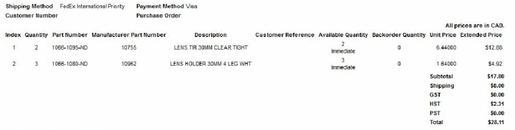
Here are the digi-key part numbers.
Excellent, thanks very much. I hadn't even realized there WAS a Digikey Canada. I'm going to start putting together the shopping list right away. This also gives me an excuse to fire up my lathe to machine the heat sink. Pls post more pix as you progress
OP
lucca brassi
Contributor
IMO :
Main problem is connection between cable and driver ! - for me .
Cable (my) is relative thick , you need enough space , and if you have to place without twisting or rolling excess cable you have done 50% of
work and to provide the user the correct functioning of also 50%.
You also have to fix heat sink inside lamp head in right position between bottom , reflector , glass ...
It is very nice if you can stationary consolidate cable with heat sink and driver - mean all three parts together in compact unit inside head.
OP
It is very nice if you can stationary consolidate cable with heat sink and driver - mean all three parts together in compact unit inside head.
It is possible to solder the cable leads directly to the driver then pot, but I decided not to go that way. I want to be able to change drivers easily. So there are two wires soldered to the driver, sticking out of the potting, (not shown). These are soldered to the cable & covered with electrical tape or wire nuts (This allows easy replacement of the driver). The power cable will have a plastic cable tie on it to keep it from pulling out of the gland, but allow it to recess into the cavity in my housing. Note this is my existing MR11HID housing not a new design.There is a small gap in the housing behind my driver. A 3 mm thick silicone foam or neoprene disk is placed here to accommodate any tolerance or gap remaining. This keeps the assembly forward, tight to the front lens. This can be seen in the LED_lamp_head.jpg I posted earlier. There is also a similar spacer between the optic holder & front glass.
It is possible to solder the cable leads directly to the driver then pot, but I decided not to go that way. I want to be able to change drivers easily. So there are two wires soldered to the driver, sticking out of the potting, (not shown). These are soldered to the cable & covered with electrical tape or wire nuts (This allows easy replacement of the driver). The power cable will have a plastic cable tie on it to keep it from pulling out of the gland, but allow it to recess into the cavity in my housing. Note this is my existing MR11HID housing not a new design.There is a small gap in the housing behind my driver. A 3 mm thick silicone foam or neoprene disk is placed here to accommodate any tolerance or gap remaining. This keeps the assembly forward, tight to the front lens. This can be seen in the LED_lamp_head.jpg I posted earlier. There is also a similar spacer between the optic holder & front glass.
OP
OP
I am not sure I understand your statement Lucca : "You also have to fix heat sink inside lamp head in right position between bottom , reflector , glass ..."
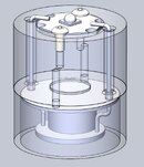
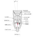
I am not using a reflector. I have selected the carclo TIR optic (lens) and holder. The holder has 4 legs that match the cut-out shape in the LED star board. The optic snap-fits into the holder. The holder has 4 legs (posts) that fit into the notches in the LED Star PCB. It is held with glue. (Hi-temp epoxy). The LED board is secured/clamped to the heat sink with 2 no.4 screws (seen in the led_core.jpg) The potted driver cup is held tight to the back of the heat sink by 2 screws. This makes one assembly to slide into the Light Head. A 3mm foam rubber disk with center holes for wires, is behind the assembly, and a 3mm foam rubber ring is places in front of optic holder. These two compress to 3 mm thickness (50%) when glass lens is secured over the 0-ring with retaining ring. So the assembly is pretty much one piece sandwiched between two pieces of silicone foam (cushion).
I am not using a reflector. I have selected the carclo TIR optic (lens) and holder. The holder has 4 legs that match the cut-out shape in the LED star board. The optic snap-fits into the holder. The holder has 4 legs (posts) that fit into the notches in the LED Star PCB. It is held with glue. (Hi-temp epoxy). The LED board is secured/clamped to the heat sink with 2 no.4 screws (seen in the led_core.jpg) The potted driver cup is held tight to the back of the heat sink by 2 screws. This makes one assembly to slide into the Light Head. A 3mm foam rubber disk with center holes for wires, is behind the assembly, and a 3mm foam rubber ring is places in front of optic holder. These two compress to 3 mm thickness (50%) when glass lens is secured over the 0-ring with retaining ring. So the assembly is pretty much one piece sandwiched between two pieces of silicone foam (cushion).
Similar threads
- Replies
- 2
- Views
- 1,294
- Replies
- 4
- Views
- 1,306
- Replies
- 2
- Views
- 1,056