Help with DIY Divelight

Please register or login

Welcome to ScubaBoard, the world's largest scuba diving community. Registration is not required to read the forums, but we encourage you to join. Joining has its benefits and enables you to participate in the discussions.

Benefits of registering include

  • Ability to post and comment on topics and discussions.
  • A Free photo gallery to share your dive photos with the world.
  • You can make this box go away

Joining is quick and easy. Log in or Register now!

Thanks Ben-
How did you make the stepped lens? I'm assuming it needs to be fairly tight tolerances and have smooth surfaces for the o-ring.
-Brad

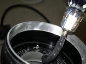
Well, I left that part out because I didn't want to discourage anybody. I used a rotary table on a milling machine. Wait! Don't leave yet!!! You don't need fancy machine tools to do this. :D 
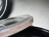
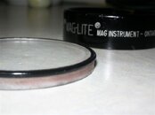
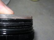
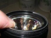
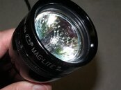
You could do this many different ways that are just as effective but take a little longer. Step one is to mark a circle on the polycarb sheet with a marker and rough-cut the disk out with a saw. It's kind of brittle so support it well or it'll fracture. Once you have an oversized somewhat-round piece cut out use a belt sander to grind it down to your marker line. I use a stationary 72" belt grinder, but a carpenters belt sander would work just fine. If you don't have a belt sander go borrow one. Flip the sander on it's back so you only have to hold the lens. Doing this part by hand would take forever. Using a sander you'll be done in 5 minutes. When you start to get close to final size start checking the fit. You want it to just slip inside the mag bezel. Be careful to sand 90 degrees to the face and back so everything is square. you don't want any taper. Take your time and you'll get a great fit without gaps. Now that you've got a perfect disk you just need to grind the step. This will require some sort of jig. If you have a router table or a drill press this should be pretty easy. For example, if using a drill press I would clamp something to the table to form a 'V' shaped fence that you could push the disk into. Then you could turn the disk keeping the cutting bit at the same depth all the way around the disk for a perfect step. Be safe and all that. I accept no liability for detached digits or other bodily trauma. :wink:

-Ben

ps - don't peel the plastic off the polycarb until you're done. It scratches easily.
 
Thanks for the details. I have a drill press and a router table; that should get me started. Lexan is cheap enough I can mess a few up to get it right. Do you know the dimensions of your step?
 
Here are the dimensions of the lens I made:
Outer diameter: 52mm
Inner diameter: 50mm

Step is cut 2mm square (2mm in from base, 2mm in from side)
O-ring used is the stock bezel o-ring moved from above lens to under lens.

When I disassembled the head to take these measurements I noticed something I had forgotten. You'll notice in the next to last picture that I've bored out the end so the bulb is recessed about 1/4". I did that to keep the bulb back away from the lens a bit. I use a piece of fat o-ring material as a spacer between the lens and bulb so the bulb is held in place. You can see it through the lens in the last picture. It doesn't do any sealing - it's just a spacer.

Hope this helps.

-Ben
 

Attachments

  • IMGP3115 (Small).JPG
    IMGP3115 (Small).JPG
    29.4 KB · Views: 85
  • IMGP3113 (Small).JPG
    IMGP3113 (Small).JPG
    28.3 KB · Views: 82
  • IMGP3117 (Small).JPG
    IMGP3117 (Small).JPG
    26.7 KB · Views: 92
  • IMGP3118 (Small).JPG
    IMGP3118 (Small).JPG
    42.3 KB · Views: 82
  • IMGP3120 (Small).JPG
    IMGP3120 (Small).JPG
    41.6 KB · Views: 78
  • IMGP3121 (Small).JPG
    IMGP3121 (Small).JPG
    42.1 KB · Views: 78
A few follow-up thoughts...

Use my measurements as a rough guide only (since I did some light machining to mine). I recommend you flatten the end of the maglite head, adjust the bore to fit your bulb if needed... Then, after all the fitting adjustments have been made to the head, and only then, measure and make the lens to fit. I say this because the bezel o-ring is only 2mm and the sealing surface is only a hair over 1mm. In other words the lens has to be a pretty close fit. So do it last, and make it a custom fit.

-Ben
 
I now realize that I am more of a "Assemble it Yourself" (AIS) type of guy rather than the "Do it Yourself" (DIY) type.

dcahill129,
If it hasn't been suggested already, you might take a look at batteryspace.com. They have batteries and chargers (of course), but they've also got some canister light parts including bare canisters + lids. Seen here.

-Ben
 
Ben, thanks for the pics. That helps a lot. Can't wait to get started.

One thought: if I kept the o-ring under the bezel, and added a new one under the lens, I would then have a double seal. Might do that.
 
Ben, thanks for the pics. That helps a lot. Can't wait to get started.

One thought: if I kept the o-ring under the bezel, and added a new one under the lens, I would then have a double seal. Might do that.

drabsab the EZ method is replace the Bezel top o-ring with a 3mm o-ring, and the one one between the head and bezel with a 2mm o-ring. I don't recall what the one in the tailcap is, but 2mm sounds right.

For mine I used both methods of sealing. I make the same type of lens as airsix, but I use a piece of 2" diameter PVC pipe and a flush cut router bit. I sanded the lighthead down with 600grit paper on my table saw. A nice smooth surface is critical.

To make the stepped lense -

Rough cut to size and hot glue 1/4" acrylic to a 8 or 9 inch long section of 2" diameter pvc pipe. The pipe will give you the right size disk, and makes a nice handle to get you're fingers away from the bit.

Use the flush cut router bit to cut the acrylic flush with the pvc pipe. Make sure the fit is right on the maglite bezel, If it's too big, sand it down until it fits just snug.

Take the ball bearing off the top of the router but and replace it with one size smaller bearing. this makes it into about a 2mm rabbiting bit. Adjust the table down so that you're only making about a 2mm in height cut, and run the acrylic disc through again. Now that your done, put the pipe and disk that are still glued together into boiling water to get the disk loose. (the glue melts) finish it up with some sandpaper and you're done.

I put o-rings on both sides to give myself a redundant seal.

Jake
 
Thanks, Jake. This sounds pretty simple.

With the LED conversion, the light isn't going to focus, so I plan to coat the threads on the head/body with silicone before putting them together. Between the o-ring and the silicone, that should be a permanent, watertight joint. So I'll have a redundant seal at the lens, but only one o-ring at the endcap. That would appear to be the weak link? Has anyone had any problems there?
 
https://www.shearwater.com/products/swift/

Back
Top Bottom