Compressor controller

Please register or login

Welcome to ScubaBoard, the world's largest scuba diving community. Registration is not required to read the forums, but we encourage you to join. Joining has its benefits and enables you to participate in the discussions.

Benefits of registering include

  • Ability to post and comment on topics and discussions.
  • A Free photo gallery to share your dive photos with the world.
  • You can make this box go away

Joining is quick and easy. Log in or Register now!

Miyaru

Technical instructor
ScubaBoard Sponsor
Scuba Instructor
Messages
1,723
Reaction score
2,079
Location
Malta
# of dives
5000 - ∞
Couple of weeks ago I got an old Bauer K14, which had spent 10 years at sea for an offshore company.
K14-start.jpeg

It was built in 1981, had a 7.5kW 3-phase engine with a manual star-delta switch and lots of rust.

I cleaned it up, changed the engine for a 3.6kW 3-phase one, added a softstarter, automatic condensate drain, oil pressure sensor & switch, and a pressure maintenance valve.
20200825_081520.jpg

Then I needed a control unit to operate the condensate drain, check the oil pressure switch and turn the compressor off once the maximum pressure has been reached.

I built it myself using an Arduino, small display, and a relay. And since components these days are dirt cheap, I also added temperature sensors which are mounted on each stage, and a Hall sensor to measure the rpm.

Turned out pretty neat. I just ran a test, filling a set of doubles from 25bar to 305bar. The oil pressure switch still needs to be set correctly:
K14controller.jpg
 
wow, that's nice!
 
G'day,
Yesterday I started to write up the requirements for a compressor monitoring and control system for my dive shop. I have one compressor running now with a second about to come online and a third waiting to be installed next year. They're old Ingersoll Rand units each with a basic contol panel.
Looking to have a headless node monitoring each compressor for room temp, and temps of the four cylinder heads out in the compressor area. Have the node power on and off an axial cooling fan for the compressor to keep things operating within the desired temperature range and alert us if it gets too hot.
Record temperatures when the compressor is given power, when the cooling fan starts and stops, plus when the compressor starts and stops. Record the compressor hours as well.
Was looking to use RPi for the nodes, but have been told Arduino might be better.
Then I want to have an RPi 4 by the fill panel in the dive shop where we can see what's going on on a HDMI screen and use a touch screen for input.
Wanting to be able to tell the system when various mainenance events have happened, and for it to warn us when they're due or overdue.
Also looking to tell the system how many air fills have been completed as it happens.
The laptop and desktop computers on our network should be able to see the information and add events also.
The idea is to have a complete record of the work done on and by the whole system.
Future enancements might include monitoring cylinder and oil pressures, outside environment, when the dump happens, and the Analox CO Clear reading.
I'd be really interested in learning more about your solution, the hardware and software used etc.
Seems you're effectively using the Arduino as a replacement for the control panel I have. I hadn't thought about going that far, but it makes sense.
Best regards, Lloyd Borrett.
 
Arduino is simpler than a Raspberry Pi, and in many cases more reliable because of the simplicity. Anything that is to run stand-alone, can probably be done the easiest with an Arduino.

The whole thing on a display is a gimmick, the only things that really count (and doesn't require a color display):
1. Stop the compressor is the oil pressure in the last stage drops (below 35bar*).
2. Drain the condensate every 15 minutes*.
3. Stop the compressor when the maximum pressure has been reached.

For option 1 I use the standard oil pressure switch that's already used on nearly all Bauer compressors. It closes above the pressure that can be set with the turn wheel. During the first few seconds of the compressor startup, low oil pressure shouldn't cut the power since it takes a couple of rotations to build up.

Connect from the ground (GND pin) to the switch, and the other switch connection goes to a digital pin, which you set as input with an internal pull-up option. Once the compressor has been running for 10 seconds, an oil pressure drop (= switch opens) will pull the input pin to HIGH, the program should then cut the power (through a relay).

For option 2 just a relay is needed. Close the relay on startup. Count 900 seconds, open the relay, count 6 seconds, close the relay. Repeat until compressor stops and open the relay.

Option 3 requires a pressure sensor. The industry standard for sensors is the current-loop: 4-20mA. AE has some pretty good sensors for roughly $25 for 250bar*, 300bar*, 400bar*. But....Arduino (or Raspberry) can't read currents, only voltages. So a current-voltage-converter is required. And since Arduino does a piss-poor job when it comes to changing an analog voltage into a digital value, I used an ADS1115. And then....it's measuring, calibrating, programming.

All nice as long as it runs standalone. One could add bluetooth or ethernet to Arduino, but this is where a Raspberry pi has benefits. For example, in my compressor room, a Raspberry Pi takes care of the following:
  1. Keep track of the pressure in the banks by measuring every 5 minutes and use rrdtool to graph it.
  2. Check who is filling tanks, by reading an NFC tag. Tags are stored in a database. The Raspberry Pi checks the tank pressure (sensor 1), if it's lower than bank 1 (sensor 2) it opens the solenoid 1 to bank 1. Next, it closes solenoid 1 and opens solenoid 2 to bank 2 (which has sensor 3). Once the final pressure has been reached, it turns off solenoid 2. The total bank volume before and after the fill are stored in the database and are used to calculate how much breathing gas was delivered.
  3. The RPi also measures the temperatures of all the tanks on the bank, which is used in calculating the practical volume with air compressibility factors.
  4. The RPi can also be used for blending: I simply select EAN32, EAN50 or EAN80, and the RPi first opens the (O2 cleaned) solenoid to the oxygen bank, waits while the tank is slowly filled to the required pressure, and then tops up with air as in 2.

fillpanel.jpeg fillpanel2.jpeg
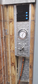
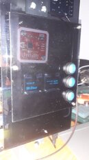
The panel and a closer look at the electronics: PN532 NFC reader, 2 OLED screen (SSD1306) and 3 menu buttons.

The RPi communicates with a hosted server for the database and rrd-data. Below is an example of the pressures. It's still slowly dropping since a check valve is not properly sealing. Still work to be done....
bankgraph.png


* Yes. Metric system. Feel free to convert to the impaired system.
 
Wow! Thanks for sharing.

In many areas you've gone way further than I've been thinking of. My focus has been on some other issues like cooling. Plus my compressors have control panels in place, though now you've got me thinking that maybe they should be made redundant in due course.

I've been writing up the requirements for a compressor monitoring and control system for my dive shop the last few days and have now incorporated the information you've shared into it.

I've been planing to use Freelancer to make contact with someone I could pay to build the solution for me.

Maybe it's a project you might be interested in doing for me? Or maybe you'd be prepared to collaborate with a developer we find in return for sharing the extra stuff I'd pay for?

I'd like to see the result winding up as an open-source project, but I'm open to other ideas.

I'd love to share my document with you, once I feel its ready, and get your expert feedback.

Best regards, Lloyd Borrett.
 
Miyaru,

I’m looking to put together a similar setup. I’ve got an arduino sitting around from another project that I’m hoping to use.

What did you use for the auto condensate drain servos?

Would you be willing to provide a photo of your drain setup along with the code to help me get started in the right direction?

Thank you!
-James
 
The ACD is the standard Bauer one, with a 220V normal-open solenoid.

The moment you turn on the compressor, the solenoid must be closed. That can be achieved by using a 5V relay controlled by the arduino.

You need a 2nd 5V relay to cut the power to the compressor, to stop the compressor when the set pressure has been reached, or when the oil pressure is not built up.
This 2nd relay can be wired into the same loop as the on/off switch that operates the relay for powering the motor.

The moment you turn on the compressor, the arduino is powered as well. The arduino closes the ACD solenoid so the pressure can build.

The oil pressure switch is a simple switch that closes above ~35bar. You can put 5V on one terminal and connect the other terminal to an arduino pin to read the voltage. 0V = low, 5V =high.

The arduino also starts a timer. If the timer has been running for 10 seconds, the arduino checks if the oil pressure pin is high. If not, there is an oil pressure problem and it opens the power relay - compressor stops.

Once the timer has reached 15 minutes, it opens the 1st relay that powers the ACD solenoid. The relay closes again after 6 seconds. Repeat.

The more complex part is measuring the pressure with the arduino. An easy solution is to use a pressure switch that opens when the set pressure has been reached.
I used a 4-20mA transducer to determine the pressure and show it on the display. The transducer uses the standard current-loop: 4mA = no pressure, 20mA = max pressure. To read that current with the arduino, an INA226 chip is used. Depending on the current (and thus pressure), the chip sends a 16bit value to the arduino. Translating that value to pressure is a job for the arduino program.

And that's all that's needed to control the compressor.

Couple of considerations:

The relays must have an optocoupler to keep the circuits to the solenoid and relay on the compressor electrically separated.
Use a separate power supply for the arduino.

Instead of using an arduino, you can also use an esp32. The programming is the same. An esp32 is equiped with WiFi, and that provides the option to use your phone instead of a display. No need to be in the noisy compressor room, and you can see on your phone if the compressor is running, what the pressure is, start or stop the compressor.

I'm still working on those options. But I'll post the code later this week from the initial arduino program.
 
Nice work!
I want a compressor for my sailboat and am thinking of building one using a purus compressor as the base.
Can I talk you into putting code on github or something?
I'd be happy to put it up if you don't want to bother...
 
https://www.shearwater.com/products/swift/

Back
Top Bottom