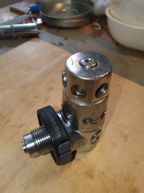
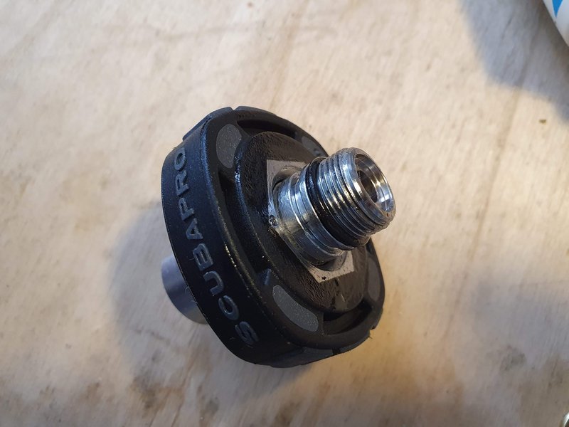
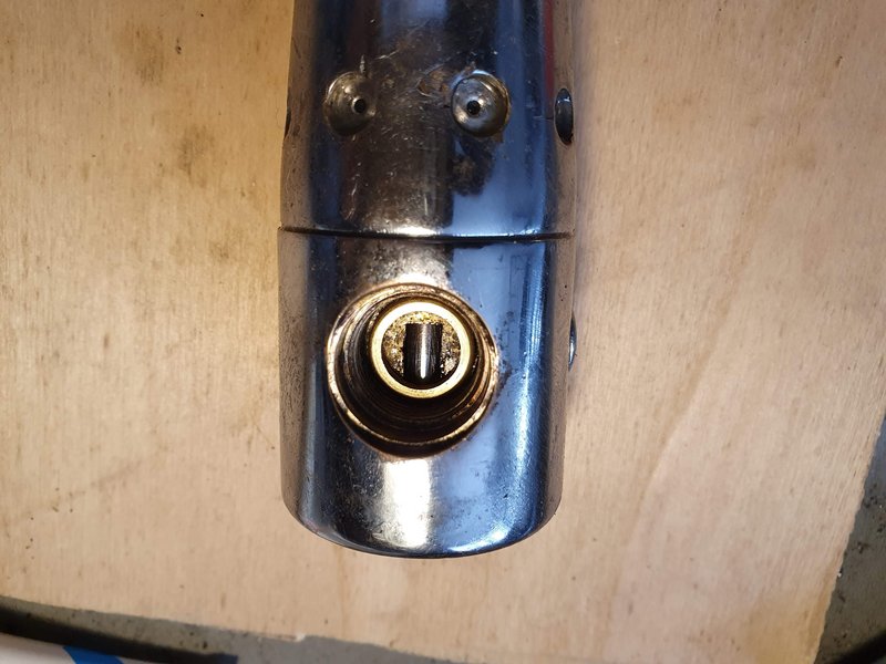
This is how it looked to me. There is indeed a groove in part 10. When I removed the yoke assembly there was no O ring in that groove so I figured no O ring in the DIN part. Since I had an "extra" O ring I put it in the groove and when I went to thread part 10 into the regulator body the O ring started to extrude so I figured nothing goes there??What I remember is this: There is indeed another groove, and the said o-ring fits in it, but once you put it there there is nothing the o-ring would seal against hence it will be just siting there doing nothing.
See the schematic below:
View attachment 686900
O-ring #12 is used to retain the knob (part #11) and o-ring #14 is used to seal the whole DIN assembly to the body of the first stage. No other o-ring is shown.
If I remember correctly, if you place that extra o-ring to the grove it will sit somewhere along the (plastic) saddle (#13) doing nothing much as the saddle and the knob are exposed to water from both sides anyway.
When you buy the DIN kit the the parts (7-11) that make up the DIN assembly it came preassembled with the O ring wheel retainer in place.
If you look at the schematic it has <30> where the groove is and [266] those are the torque setting numbers....I don't see any O ring there??


