Mares Puck PC Cable

Please register or login

Welcome to ScubaBoard, the world's largest scuba diving community. Registration is not required to read the forums, but we encourage you to join. Joining has its benefits and enables you to participate in the discussions.

Benefits of registering include

  • Ability to post and comment on topics and discussions.
  • A Free photo gallery to share your dive photos with the world.
  • You can make this box go away

Joining is quick and easy. Log in or Register now!

I finally got all the parts I ordered for this. Gotta track down my breadboard to assemble it for testing. Still not sure which terminals are +/- on the puck itself.

Any help in that area would be appreciated. Gonna be a busy week, but if I can get some help with that aspect, I'll try and get it laid out and tested. Once I confirm that it works, I'll button it all together, and check back to see if anybody needs one made.
 
When you put the puck on pc link mode it activates the terminals, take a volmeter and measure the voltage and you will find the correct polarity
 
I was not aware that it would actually output a voltage when activated. Thanks, I'll give that a try.
 
Hello,
I am very interrested in the electronic circuit schematic of the USB cable between the PC and the mares puck.
I do not understand exactly how the electronic circuits (like CP2102) are connected.
Can you send me the picture with the schematic because the link on the first page is dead ?

Think you and sorry for my poor english
Lionel
 
There is a problem with the business model. Well, it is their business, finally.

If the cable is cheaper, or they release the model, more people will be interested to buy the Mares Puck.
Maybe they can charge a little more with the computer plus the cable included... A little more

Paul, from Chile
 
Hello,
I am very interrested in the electronic circuit schematic of the USB cable between the PC and the mares puck.
I do not understand exactly how the electronic circuits (like CP2102) are connected.
Can you send me the picture with the schematic because the link on the first page is dead ?

Think you and sorry for my poor english
Lionel

Lionel,

Sorry for the slow reply, I've been really busy. I still haven't actually tested this circuit, but it should work as depicted. Here is the schematic. I thought I would have to upload the file again, but it appears that it remembers my uploads. If the image is deleted again it will be much easier to post.

- Bryce
 

Attachments

  • Mares Puck Schematic (Big).jpg
    Mares Puck Schematic (Big).jpg
    34.5 KB · Views: 2,124
Hi all!


I recently bought mares Puck (not puck pro) and I'm quite happy with it, but the cost of PC cable is insane (it costs more than I paid for new Puck:wink: 
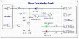
) so i decided to try and build interface based on your schematic (I already had the USB controller). Unfortunately it didn't work (at least not yet).

1. When the Puck is either not connected or not in PC mode, the green light will be on. This is because the Puck tri-states (lets float) its DIO pin. Without anything to pull the DIO pin high, the 100k resistor pulls the NAND inputs low (pins 1 and 2) which then drive pin 7 high. If the Drak is not in SUSPEND (sleeping or not enumerated on the USB) then pin 12 of the CP2102 will be low which causes current to flow through the green LED, lighting it.
This works as expected.

2. When the Puck is connected and put into PC mode, then the DIO pin is pulled high. This pulls NAND inputs high which causes pin 7 to be pulled low. This lights the red LED because current now flows from CP2102 pin 11 to pin 7 through the LED.
This also works

3. The PC then sends a message to the Puck. Pin 26 is pulled high normally (its idle state) which allows DIO to be pulled high. When Pin 26 is pulled low (when sending data), current flows through the S7 diode pulling the DIO pin low (to about the forward voltage of the diode).
This doesn't work. I checked pin 26 voltage while software is tying to communicate with puck. It doesn't go low, so maybe there is something wrong here?

4. When receiving data, pin 26 stays high, and DIO is toggled by the Puck computer. When DIO is high, pin 7 is low and pin 5 is idling high. This makes pin 25 high. When DIO is pulled low by the Puck, pin 7 (pin 6) is high and because pin 5 is also high pin 25 is toggled low.

This setup uses TX pin 26 as a switch for bi-directional data transfer - when held high, RX can receive. When data is sent and received the LEDs should flash from green to red based on the current state of the DIO line. This circuit also creates something like an open collector connection between the two devices. The data transfer speed is 38400 baud. I'm not sure if just using an open-collector output tied to the RX line would work. The PC would then have a loop-back where it received everything it sent. This depends on the computer software and what it does with the extra data.


Rest didn't work, here is what happens:
1. USB cable connected: red diode OFF, green ON
2. Puck connected in PC mode: red diode ON, green OFF
3. I run mares connection wizzard, when it tries to find Puck red diode goes down (green is off all the time) so i think pin 12 goes high.
4. Software goes "thinking" for few moments and than displays that device is not connected. However i think that "something" is happening because if I do those steps without puck connected software instantly displays information that device is not connected.


Has anyone done more research? maybe there are some adjustments that should be made in this schema?
 
Hi,
I'm in the same situation and would like to build my own cable.
How did you manage the connection between you circuit and the computer pins ? I can't find a plug that fits the computer pin...
Thanks
 
I am about to build this device. Will let you know whether I experience the same problem
An important issue is the choice of Schmidt NAND chip. Make absolutely shure the chip you use can operate at 3V power supply and if possible even lower. Some newer CMOS Shmidt NAND chips operate with supply voltages down to 2V. This is what you need. Some other CMOS equivalents operate only from 5V supply voltage and higher; in these chips switching at 3V is not guaranteed to give reliable outputs.
Kind regards,
wf
 
https://www.shearwater.com/products/peregrine/

Back
Top Bottom