You are using an out of date browser. It may not display this or other websites correctly.
You should upgrade or use an alternative browser.
You should upgrade or use an alternative browser.
Mares Puck PC Cable
- Thread starter Moerby
- Start date
Please register or login
Welcome to ScubaBoard, the world's largest scuba diving community. Registration is not required to read the forums, but we encourage you to join. Joining has its benefits and enables you to participate in the discussions.
Benefits of registering include
- Ability to post and comment on topics and discussions.
- A Free photo gallery to share your dive photos with the world.
- You can make this box go away
jwhferguson
Registered
One thing to keep in mind with this gadget is that it uses a lot of battery power. Use it carefully, doing downloads of dive data possibly only after each multiple-dive trip. There are several dive computers with this problem, even Suunto. I am not shure why, because the Puck circuit above appears to have an input impedance of soime 100 kohm. However, this is only the static resistant impedance and some of the current can possibly go through the USB microboard, not visible under static conditions.
Consider the software package "Subsurface", an open source program that interacts perfectly with the Puck line of computers (and many others) and that runs on Linux, Mac as well as Windows. In my personal opinion it is great. Check it on the Web.
Kind regards,
willemf
Consider the software package "Subsurface", an open source program that interacts perfectly with the Puck line of computers (and many others) and that runs on Linux, Mac as well as Windows. In my personal opinion it is great. Check it on the Web.
Kind regards,
willemf
Bryscus
Registered
AndrewStick
Registered
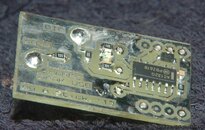
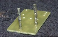
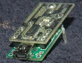
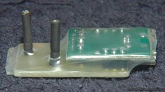
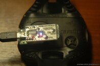
Thank you!Looks awesome! I'm glad someone was finally able to make a nice homebrew board. Any chance you can upload the gerber/image you used to etch the board?
Of course, PM me your e-mail.
Thank you!
Of course, PM me your e-mail.
Hi AndrewStick, any chance you would be willing to make the design of the PCB open, perhaps posting the gerber file here? I am pretty sure more people would benefit from it, myself included
AndrewStick
Registered
Sure, I will give it to anyone who wants. But only after "user license" agreement (only for personal/friends use, not for sale, etc.)any chance you would be willing to make the design of the PCB open
I recently bought mares Puck (not puck pro) and I'm quite happy with it, but the cost of PC cable is insane (it costs more than I paid for new Puck) so i decided to try and build interface based on your schematic (I already had the USB controller). Unfortunately it didn't work (at least not yet).
"Originally Posted by BryscusThis works as expected.
1. When the Puck is either not connected or not in PC mode, the green light will be on. This is because the Puck tri-states (lets float) its DIO pin. Without anything to pull the DIO pin high, the 100k resistor pulls the NAND inputs low (pins 1 and 2) which then drive pin 7 high. If the Drak is not in SUSPEND (sleeping or not enumerated on the USB) then pin 12 of the CP2102 will be low which causes current to flow through the green LED, lighting it."
"Originally Posted by BryscusThis also works
2. When the Puck is connected and put into PC mode, then the DIO pin is pulled high. This pulls NAND inputs high which causes pin 7 to be pulled low. This lights the red LED because current now flows from CP2102 pin 11 to pin 7 through the LED."
"Originally Posted by BryscusThis doesn't work. I checked pin 26 voltage while software is tying to communicate with puck. It doesn't go low, so maybe there is something wrong here?
3. The PC then sends a message to the Puck. Pin 26 is pulled high normally (its idle state) which allows DIO to be pulled high. When Pin 26 is pulled low (when sending data), current flows through the S7 diode pulling the DIO pin low (to about the forward voltage of the diode)."
"Originally Posted by BryscusRest didn't work, here is what happens:
4. When receiving data, pin 26 stays high, and DIO is toggled by the Puck computer. When DIO is high, pin 7 is low and pin 5 is idling high. This makes pin 25 high. When DIO is pulled low by the Puck, pin 7 (pin 6) is high and because pin 5 is also high pin 25 is toggled low.
This setup uses TX pin 26 as a switch for bi-directional data transfer - when held high, RX can receive. When data is sent and received the LEDs should flash from green to red based on the current state of the DIO line. This circuit also creates something like an open collector connection between the two devices. The data transfer speed is 38400 baud. I'm not sure if just using an open-collector output tied to the RX line would work. The PC would then have a loop-back where it received everything it sent. This depends on the computer software and what it does with the extra data."
1. USB cable connected: red diode OFF, green ON
2. Puck connected in PC mode: red diode ON, green OFF
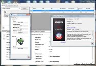
3. I run mares connection wizzard, when it tries to find Puck red diode goes down (green is off all the time) so i think pin 12 goes high.
4. Software goes "thinking" for few moments and than displays that device is not connected. However i think that "something" is happening because if I do those steps without puck connected software instantly displays information that device is not connected.
Has anyone done more research? maybe there are some adjustments that should be made in this schema?
It's been while since my previous post, but I didn't give up I just didn't have time to try this again (until now
1. Interface Active, Puck not connected - green diode ON - OK
2. Interface Active, Puck connected in PC mode - red diode ON - OK
3. Trying to connect to Mares software - red diode ON all the time, green diode is flashing with frequency ~1s. After few seconds software displays information that it is unable to connect to Puck
It looks like the computer is trying to connect to PUCK (green diode flashing) but There is no communication form Puck or there are errors in communication. I don't understand why red diode does not go down when green goes up I would expect them to lit one at a time. I double-checked (even triple-checked
Only differences are that I'm using 74HC132N not a MC74AC132NG (I don't know what is the difference between HC and AC) and that I'm using standard 1N4148 diode instead of BAT42 (I also don't know the difference). Could those things have an impact on this circuit?
If anyone is interested I can provide a picture of my circuit - it's on a prototyping board so it's not that nice
Any tips or help appreciated
AndrewStick
Registered
I think that is the answer. BAT42 is a Schottky diode unlike 1N4148I'm using standard 1N4148 diode instead of BAT42 (I also don't know the difference). Could those things have an impact on this circuit?
I think that is the answer. BAT42 is a Schottky diode unlike 1N4148
Thanks for the tip I changed diode to BAT85 (replacement for BAT42) but it didn't help
Thing that wonders me is that red diode is not going down when green diode blinks - how should it work?
AndrewStick
Registered
Now I have no idea, bro. You are able to solder SMD components? I can send you documents of my board, that works well.
Similar threads
- Replies
- 3
- Views
- 759
- Replies
- 0
- Views
- 503
- Replies
- 6
- Views
- 1,185
- Replies
- 2
- Views
- 631


