this is what i am trying to build. I will post pics later on but i would like to find all the parts first
View attachment 46423 thankyou to the person who posted this, i have moved things around to suit me.
Great drawings, always a good start. IMHO suggest some small changes.
What is the size, make and model of your compressor? you need this for filter sizing.
Starting with the downstream side of system;
1. Suggest add a non return valve after the separator. That way you can drain any water in separator without affecting the chemical charge in the filter.
2. Suggest add a water vapour visual indicator after the filter but before the BPR £30.00 ($60.00)
3. Suggest add pressure gauge (upstream of the BPR) or on separator for ease of fitment to know BPR pressure setting at all times (say 150-180barg) UK now work on a water vapour of less than 25Mg /m3 for stored gas over 300barg so you will need both this and the visual indicator to achieve this, also possible an increase in the BPR pressure setting or you run system blind and have to resort to a WAG for filter chemical change out times.
4. Filter size and type: For UK suggest Bauer type filters as they are biggest in diameter 100mm shells and use 70mm cartridges, they have the largest surface area of chemical, largest jet area and the largest amount of chemical per filter. In USA suggest MAKO type filters 95mm diam use 63mm filters. Both offer ease of filter availability and both offer repack stainless cartridges options for you to repack with your own filter chemical. (price of filter is dependant on barrel length)
5. Micronic filter on filter outlet not specified, but should read 2mu
From a safety point of view I would add some concerns.
6. On the vertical manifold non return valves are missing, should have (3) three. It should NOT be possible to transfill oxygen from the storage banks back into air banks or visa versa. Also the single greatest concern is the lack of non return valve to the inlet of manifold from the compressor IMHO this has to have a non return valve to avoid filling the filter tower with pure oxygen. While I understand the drawing shows valves fitted and as you cannot use ¼ turn type valves with oxygen so there is no visual indication of valves position, open or closed. As a “filling monkey” myself I can guarantee I would cock it up and leave a valve open, besides it saves having to keep on twisting the things to reassure yourself they are in the correct on or off position.
A quick note:
For the UK and EU countries, here is where we differ to the USA and only if you intend to sell the product i.e. you are a dive shop or commercial compressor station including UK type diving clubs such as BSAC SAA etc. Here is the problem:
7. The second manifold C needs non-return valves to the outlets to avoid back filling. If an air cylinder is being filled, to avoid any back fill with say a dirty air or nitrox or even a partially filled oxygen PP cylinder prior to air being opened at the same time.
8. However if they are both nitrox cylinders, you now do need the backfill ability to be able to measure the residual nitrox in the cylinder/s in the first place.
9. The agreed solution within UK HSE for commercial set ups is to have two separate and independent systems ie another manifold just for air cylinder filling!.
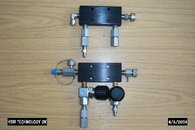
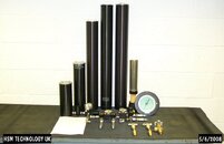
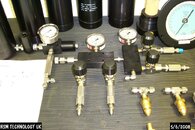
Enclosed below is a couple of pictures from your drawing I set up on the workbench to show the actual layout, and the ease of the "Mix and Match" fittings.
If you need more detail let me know.
As for suppliers these product are distributed mostly to the trade so the parts should be available from you local dive shop both UK and USA. We are an OEM engineering supplier we have no web site either UK or USA. If not available we can supply direct or if any problems. My contact in UK is: HSM Engineering Technology Ltd.
Unit 3-5 Beaumont Court. Belton Park Industrial Estate. Loughborough LE11 5DA England. tel: +44 (0)1509 211233 fax: +44 (0) 1509 269061
email is
iain@hsm-engineering.demon.co.uk


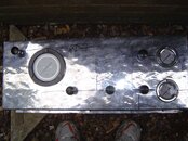
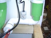
 The plate is being bent into shape this week.I have alot of parts valves ,pressure gauges,2@230bar tanks 50l,1@300bar 68l.Its a start ..Ian-hsm i will cotact you when money is better too many bills this month .