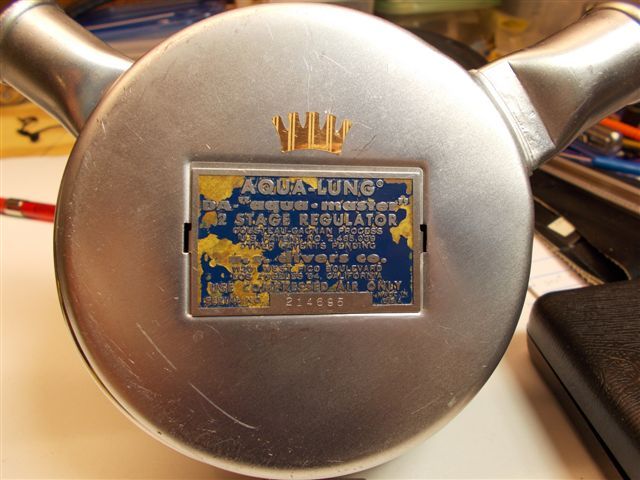
I just rebuild an Aqua Master for a friend of mine (who coincidentally is a rep for Aqua Lung).
It has been a little while since I worked on a non-balanced Aqua Master so I decided to publish some of the IP versus tank pressure data. I have taken this data before, but not as precisely and in as many increments.
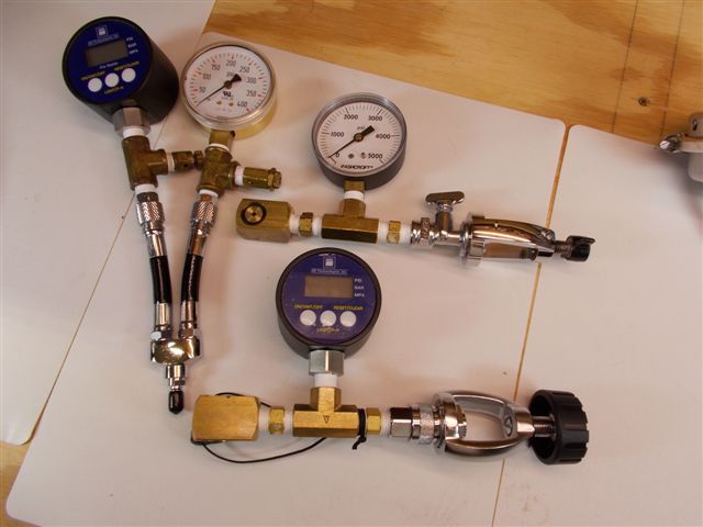
I have digital pressure gauges for tank pressure and intermediate pressure (IP). They have both been calibrated against a calibration gauge and their maximum error of both was less than 1% (0.62% and 0.74% respectively).
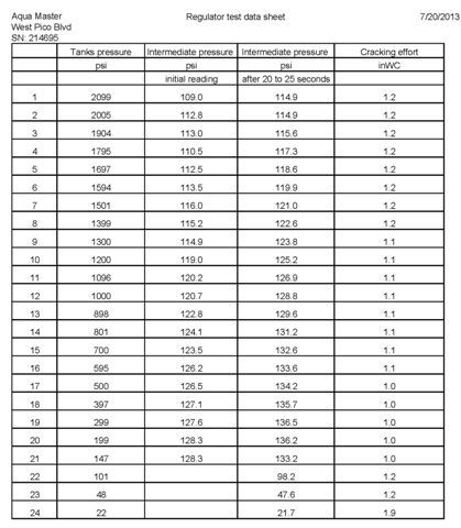
I collected data a couple of times, but I am only including the data after the last IP adjustment. I am also including the cracking effort.
The first few times that I collected data the cracking effort was on average about 0.2inWC lower, but that was without the band clamp. Tightening the band clap (clamping hard on the diaphragm) will raise the cracking effort. After this test I adjusted the band clamp some.
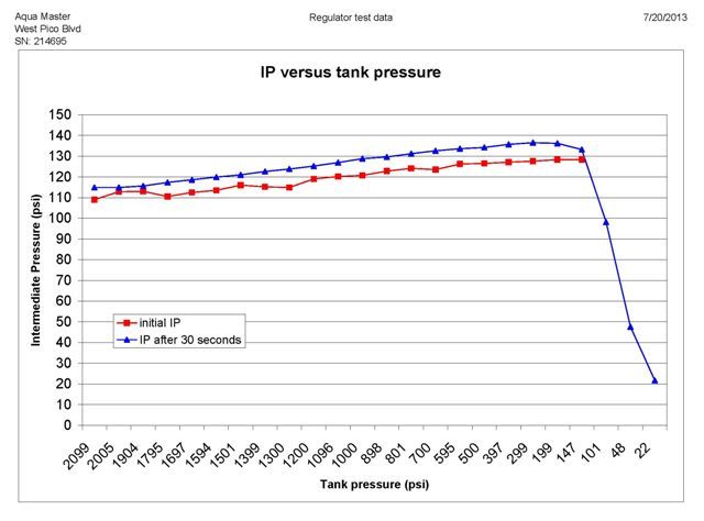
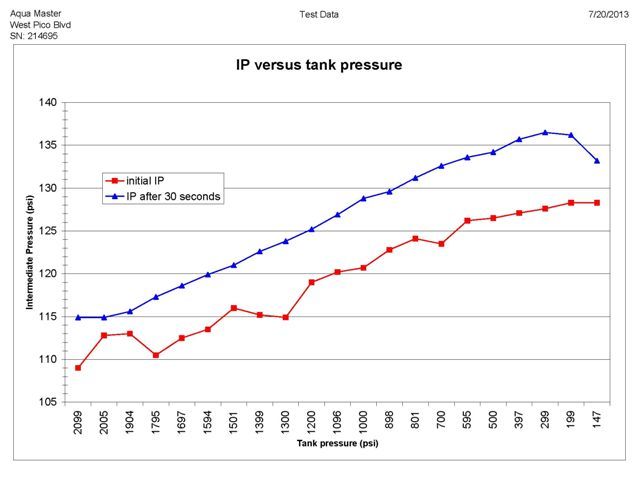
Notice that the IP raises 26.6 psi when the tank pressure drops from 2100 psi to about 300 psi. The pressure change in fairly linear (above tank pressure of 300 psi): approximately 1.48 psi increase per 100 psi tank pressure drop.
Also notice that (approximately) below 300 psi tank pressure, the IP is not linear. At some point (around 145 psi) the first stage just opens and the IP reading is the same as the tank pressure.
If I extrapolate to a full tank (2475 psi), I would say that the initial IP would be around 106 psi. That is an IP change of about 30 psi from a full to an empty tank.
I own one Aqua Master that I will try to take some more data later and I will post it.
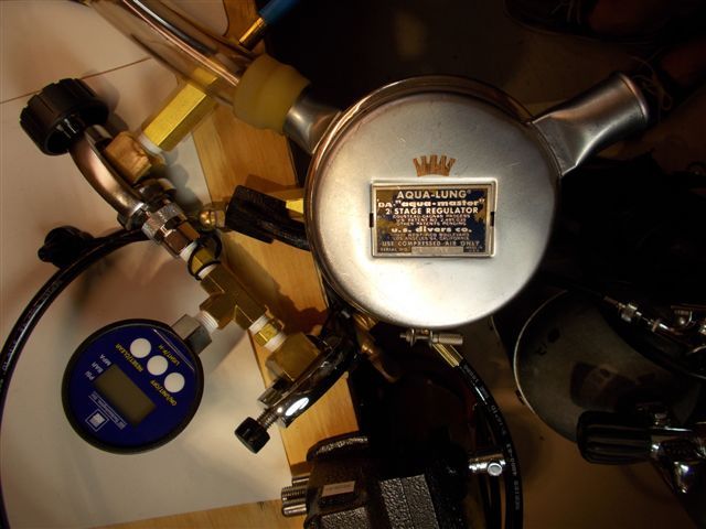
I am also posting pictures of my test set up and my regulator work bench. I just redid my work bench, cleaned, and organized a lot of the parts containers, so I decided I needed to take pictures to remind me how it is supposed to look when it is relatively clean. The regulator on the left is a PRAM, not related to this test.
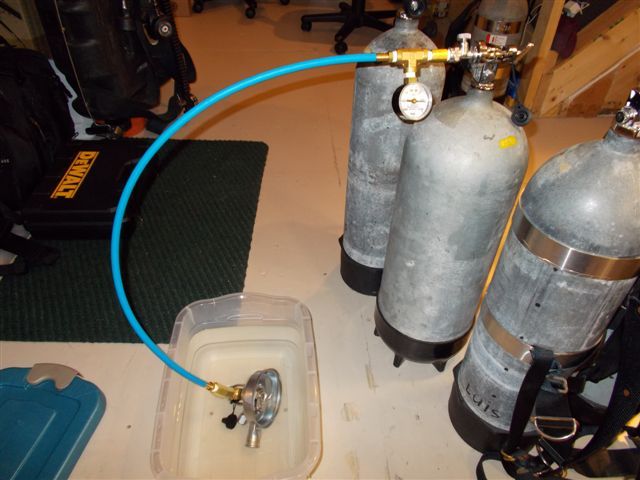
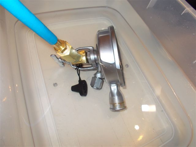
I am using several high pressure hoses in series (and my valve test stand) in order to have a reasonable size pressure reservoir after I close the tank valve. I dont have a high pressure regulator to set the supply pressure by just dialing a knob, so I just use all the hose length as a pressure reservoir that I can adjust the input pressure for it test data point.
There is about a 5 to 7 psi IP drift from initial IP recovery until it locks. You may notice that some of the initial IP data collection (the red data points in the graph) is not smooth. The reading is constantly changing at that stage; therefore taking some of the initial IP data is not always precise. Once the pressure locks the data (shown in blue) is much more accurate.


