Can you identify this coalescer and auto drain system? Trying to rebuild.

Please register or login

Welcome to ScubaBoard, the world's largest scuba diving community. Registration is not required to read the forums, but we encourage you to join. Joining has its benefits and enables you to participate in the discussions.

Benefits of registering include

  • Ability to post and comment on topics and discussions.
  • A Free photo gallery to share your dive photos with the world.
  • You can make this box go away

Joining is quick and easy. Log in or Register now!

tmassey

Contributor
Messages
962
Reaction score
1,531
Location
Shelby Township, MI USA
# of dives
500 - 999
Hello!

I am the new owner of a used Poseidon compressor. It builds pressure (yay!) and the auto-drains operate (10 seconds every 12 or so minutes). However, the auto-drain manifold does not seem to operate the way that it's supposed to. So I'm trying to figure this out, which starts with figuring out what exactly this thing is.

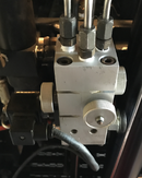
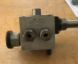
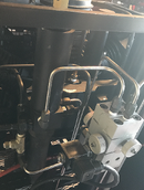
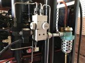
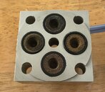
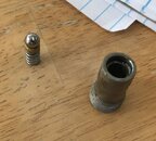
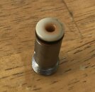
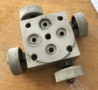
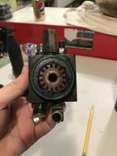
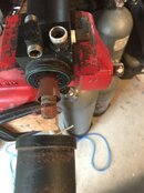
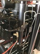
I've never seen an auto-drain system like this. I've attached some photos. The first is the auto-drain manifold on the compressor. The next is the only identification information I could find--and it seems that the second and third line are simply industry standard pressure and material labels. The last one is of the coalescer to the left of the drain manifold: I can't identify this one, either. If anyone could give me a name that would be great, and if anyone has any documentation I would be tremendously grateful.

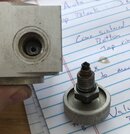
The drain system seems quite complex. There are four knobs, one on each side. I spoke to Dana at Poseidon Air in VT. He stated these were valves to bypass the solenoid for manual drain. Unfortunately, at least some of them were stuck closed. So he suggested taking it apart and cleaning it. I've done so, and found a series of parts that could use some possible replacment, espeically o-rings. But with no idea of what this thing is, it's difficult to be certain of o-ring sizes and types, etc.

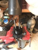
In addition, I'm getting stuff out of this thing that can only be described as chocolate-pudding-like. Yum. I think the coalescer is in serious need of attention -- at least heavy-duty cleaning. Dana said to loosen the knurled collar near the middle, but it's too tight: I can't get it off with a strap wrench and I'll have to find a pair of pliers big enough. I'm not eager to disconnect the myriad of tubes connected to this thing.

Like I said, the drains and coalescer seem quite complex. There is a drain after each stage (it's a 3-stage compressor), each of which go through the coalescer and into the drain manifold, and a fourth one coming from a coalescer in the bottom of the filter canister. There's all kinds of gas attachment points all over both the coalescer and the manifold, and the manifold has lots of valves, too! (The coalescers I'm used to seeing are one in, one out and one drain, and the drain manifolds I'm used to have external check valves and no manual valves.)

The picture of the coalescer is somewhat hard to see: the coalescer is painted black like everything on this Poseidon compressor... It's a relatively narrow tube, maybe 14" tall and 2" in diameter. The top half is cylindrical, with the final safety relief valve in the top. There is a square section mabye 1" tall in the middle, with the knurled collar screwed in immediately below this. The bottom half tapers like a cone to the final drain point in the bottom.

Again, thank you for any help you might be able to give me in identifying these two devices. I would appreciate any info you might have. Please ask any questions you have: I have *lots* more photos and notes... :)
 

Attachments

  • DrainOnCompressor.png
    DrainOnCompressor.png
    693.8 KB · Views: 258
  • DrainNumbers.png
    DrainNumbers.png
    638.7 KB · Views: 251
  • DrainAndCoalescer.png
    DrainAndCoalescer.png
    1.1 MB · Views: 242
You've already identified this out of production drain system. Sometimes it pays to do some research to find out if parts are available for something before you by it. Unless someone has a stock pile of parts, I'm afraid you are out of luck. If the drain still works, use it until it fails and then replace with an after market unit. Might have to do some replumbing. I have no idea if L.L. Burns Specialties is still in business, in some form, but Danny Burns was a big distributor for Poseidon units back in the day.
 
Yes i have a parts list with numbers that i can photo copy for you.
You dont say what is wrong with yours,So i will make a guess.

You will have to get some bits from a local bearing shop
1 Some 6mm ball bearings just the balls, { the old ones will have rust pit marks] Qty 4
2 some orings 12X2.5 Qty 4
3 Orings 15.6X1.78 Qty 4

From a local hose shop

One of your charging hoses get a adaptor so one end fits your cylinder & the other end adaptor with a metric 6s fitting they may also know this as 6 heavy

Dont run compressor
Disconect the 3 pipes on top of the block & also the port that has a blanking cap
make sure that you close the 4 taps
Connect the cylinder at 3000psi in turn to each port
each port will hold the full psi & not leak out of the drain port on the unloader block
In turn test each of the 4 ports .
With luck it will be just one that is leaking pass.

Get back with how you get on and i will tell you how to change the rusted leaking balls.

Some place i have another parts list that gives bauer part number for this unloader block
But i cant find it now

Colin
 
Windyairman, thank you *so* much for your reply! Out of production or not, *somebody* had to know what this is and how it works! And thank you for the second reply: there *are* three types of o-rings in the drain manifold... I'll get in touch with your off-thread on how I can get any documentation you might be able to give me!

The problem I had was that the manual drain valves did not seem to work. When I first ran the compressor, it wouldn't build past 400 PSI. That's because I had all four valves in the drain block wide open. So the question then became not why didn't it go past 400 PSI, but why did I *get* to 400 PSI! :) That's what drove me to disassemble and clean it.

After I put everything back together, the valves seemed to do things! With all four valves open, the first stage gauge stopped at 75 PSI. After closing the 9 o'clock valve (see DrainOnCompressor above), it went up to 80PSI and stayed there. The output gauge is off the pin, but still low. After closing the 12 o'clock valve, it went to 800 PSI (IIRC). And after closing the 6 o'clock valve it built all the way up to 4600 PSI (when the pressure switch turned it off).

I did examine the ball bearings. They all looked shiny and smooth. However, the white plastic housing of two of the four valves remained stuck in the block and I could not figure out how to get them out. Is there a way to get them out? There doesn't seem to be any way to push or pull them...

Right now my biggest question is this: There are four tubes that go into the block (3 on top, 1 on bottom) and four valves (plus the big drain pipe). That would lead me to assume that each valve controls one of each of the tubes. However, the fourth valve (3 o'clock) seems to do nothing. So is there a problem with the valve or with my assumption--and then how does that fourth tube work?

I've got a lot of other technical/operational/curiosity questions. But I'll restrain myself until I get a chance to go over the documentation, etc. and continue to work through the process -- and the steps Windyairman added too!

Again, thank you for your help. And thank you to anyone else who might have more to contribute!
 
Tonight I took the coalescer off and cleaned it. It is indeed a 2-in-1 coalescer that has been mentioned with other Poseidon compressors on SB. I'm going to write up some details, mainly to try to help someone else who might be in a similar position to me in the future. (SB as blog...) I've also got some questions if anyone can shed some light on what is going on.

TL;DR: 3 questions: Why is the output of the second stage teed off straight to the drain? Does the upper (high-pressure) coalescer chamber have an o-ring to seal? And after cleaning the coalescer and the auto-drain manifold block, is there anything else that I should clean/check/lubricate/etc.?


There are two tubes each on each side of the coalescer as it is mounted. The two on the left come from the output of the second stage and lead to the input of the third stage, and drain into the bottom half of the coalescer, where a tube exits from the bottom and goes into the drain block. However, the air output (the rear of the two left tubes) actually tees vertically: the top goes to the third stage, and the bottom *also* goes to the *bottom* of the drain block. Why?!? Like I said, the drain from the bottom of the coalescer already goes to the top of the drain block, so why tee and plumb the air output of that same chamber that also goes into the third stage into the drain block too?

For the bottom half of the coalescer, within the chamber the air comes out of a series of vanes radially around the outer circumference of the top of the chamber (where the incoming air and water enter) and there is a plastic stem and cover and sintered metal filter screwed into the center of the top of the chamber (where the ideally dry air exits). There is a face-sealed o-ring that the bottom housing presses against, with a collar that tightens that bottom housing against the middle block.

The two tubes on the right side of the coalescer come from the output of the third stage and lead to the input of the filter stack. There is a tube that comes out the front of the coalescer and goes to the drain block. Also on the right is what seems to be a relief valve. I believe that this is the OPV for the second stage. It is stamped "50" (50 Bar, I assume), and nothing else. (There is another relief valve on the head of the second stage, which I believe is the OPV for the *first* stage, and of course the third stage OPV is the relief valve in the top of the coalescer.)

For the top half of the coalescer, there are two tubes that extend inside from the middle block into the chamber. One is shorter and the top of the tube had been pinched off: There are two small holes in the side (which is where the incoming air and water enters the chamber). The other tube is a little longer and open at the top (which is where the ideally dry air exits). There is also a hole in the base of the chamber, which leads to the drain.

My question here is: there does not seem to be an o-ring sealing this chamber: just maybe 1.25" or so of thread, and it looks like straight thread, too. And this is the highest pressure chamber. Is that right, no o-ring? It wasn't leaking before I took it apart, and I'm pretty sure I didn't lose an o-ring...

There is some information stamped into the top chamber housing:

POSEIDON WIEN
ALMGSI1 F31 CH4143
350BAR 0.1LTR 1986
FAB NR 20690

The coalescer really looked reasonably clean inside: oily of course, but certainly no chocolate-pudding-like sludge. The drain block was similar. Maybe I've blown out all of the sludge by now? But the real question is: while I'm at it, what else should I clean out? And what else should I be examining and addressing?

I've taken lots of photos: before, during and after. I'll try to select a few key ones and post them here so that others can follow along. But if you have *ANY* questions or want to see something specific, just ask!

Again, thank you very much for your time in checking out my posts. I really appreciate it.
 
Here are some more photos.

Auto-drain manifold:
= The drain block and where the output goes: to a low-pressure moisture separator.
= The sintered filters in the top part of the drain block.
= The o-rings used in the filter
= The top of the middle section: the valve block itself
= If you take out one of those inserts in the valve block, this is what you get (when the plastic part is stuck inside)
= Here's what you get if the plastic part comes out! The BB and spring is inside.
= The valve stem and a look inside
= The bottom of the (middle) valve block and the top of the (bottom) solenoid block
 

Attachments

  • ValveStem.jpg
    ValveStem.jpg
    79.8 KB · Views: 199
  • DrainAndOutput.jpg
    DrainAndOutput.jpg
    93.5 KB · Views: 192
  • DrainSinteredFilters.jpg
    DrainSinteredFilters.jpg
    95.7 KB · Views: 204
  • DrainBlockMiddleAndBottom.jpg
    DrainBlockMiddleAndBottom.jpg
    57.5 KB · Views: 196
  • SinteredFilterWithORings.jpg
    SinteredFilterWithORings.jpg
    76.6 KB · Views: 198
  • ValveBodyPartialGuts.jpg
    ValveBodyPartialGuts.jpg
    79.3 KB · Views: 195
  • ValveBodyFullGuts.jpg
    ValveBodyFullGuts.jpg
    76.1 KB · Views: 196
  • ValveBodyTop.jpg
    ValveBodyTop.jpg
    102.7 KB · Views: 195
Coalescer photos

= Coalescer on compressor from Right with auto-drain manifold removed
= Coalescer on compressor from Left with auto-drain manifold removed
= The bottom of the middle section of the 2-in-1 coalescer. This is the lower pressure portion.
= The bottom of the middle section with the filters in place
= The top of the middle section showing the tubes in and out of the chamber
 

Attachments

  • LowerChamberTop.jpg
    LowerChamberTop.jpg
    62.3 KB · Views: 195
  • LowerChamberWithFilter.jpg
    LowerChamberWithFilter.jpg
    68.2 KB · Views: 185
  • CoalescerFromR-DrainRemoved.jpg
    CoalescerFromR-DrainRemoved.jpg
    77.4 KB · Views: 208
  • UpperChamberBottom.jpg
    UpperChamberBottom.jpg
    76.9 KB · Views: 187
  • CoalescerFromL-DrainRemoved.jpg
    CoalescerFromL-DrainRemoved.jpg
    99.2 KB · Views: 206
You can still get parts. Pretty sure you can get parts through Bauer. Posideon is Bauer’s economy models.
 
For the past five years I've been using needle valves to manually drain, which has worked just fine. But this winter I had an issue with my compressor, which led to me (successfully!) replacing the second and third stage valves. This was a pretty unnerving experience for me, and now that it's done and everything is working, I'm feeling pretty excited--like a superhero. :) It inspired me to re-tackle these drains.

That is, until I took the first channel apart again. When I pulled out the plastic valve out, it had a tiny o-ring, and that just disintegrated in my hand. That was enough for me: I really didn't want to have to work my way through this on my own if I could help it.

So, I called up Poseidon Air in Vermont. I had done that when I took the drains off 5 years ago, but I didn't hear anything back from them. But this time I was more persistent, and after a couple of calls I was able to get in touch with them. (As an aside, he said that he can be hard to get in touch with, but to keep trying: so if you're in the same position, be persistent.)

I believe he said that these drains were indeed built by Bauer, but not the same division that built the compressor block (Austria), and that they were not popular. They were discontinued some time ago, and parts can be difficult to get -- but that he *does* have parts for them. And given that I've had them apart, there really isn't anything else to do but to send them to him and let him have a go at them.

So I did. And a couple of weeks and a couple of hundred dollars later, I got them back. From the outside, they look exactly the same, and I'm not even thinking about peeking inside. But back on the compressor it goes.

Installing was straightforward: take my manual needle valves off, put the auto-drain on, and reconnect all *four* tubes: one from each drain, and an extra tap from the after-second-stage coalescer, which is the gas that the solenoid controls to actuate the drains. I had previously capped that off, but now I uncapped it and used the original tube to connect. I also took the opportunity to clean the exhaust muffler that the auto-drain feeds into.

Once again, a bit of trepidation while I press the big green button... And I'm greeted by the sound of air wooshing out of the auto-drain. Which it's supposed to: it opens for 8 seconds when you turn the compressor on. And then it closed, and I'm just left with the sound of the compressor! Excellent!

So I let the compressor run. I then sit there waiting to hear the sound of the drains opening sometime in the future. But I *don't* hear it. So I use the wheels to manually drain the compressor and keep going. I let it run for 30 or so minutes, and I never hear the drains... But the last time I did the manual drain, I noticed that the pressure in the second stage stayed low for a number of seconds, then jumped up like it's supposed to when you close the drain. It dawned on me: the auto-drains might actually be working, but I just can't *hear* the drains. (When I talked to Poseidon Air later, that was his thought as well.) I needed to stop at that point, so I couldn't investigate further. Next time when I run the compressor I'll watch the pressure gauges and make sure that the drain is indeed working as I expect. It certainly *should* be: it works just fine when I fire up the compressor. But we'll see.

It's really nice to have the drains back on the compressor: it *looks* neater, if nothing else. The drains were tested in Vermont and worked 100% correctly, so I'm optimistic. I'll update this as soon as I learn more.
 
https://www.shearwater.com/products/swift/

Back
Top Bottom