Nitrox/Trimix & CO analyzer

Please register or login

Welcome to ScubaBoard, the world's largest scuba diving community. Registration is not required to read the forums, but we encourage you to join. Joining has its benefits and enables you to participate in the discussions.

Benefits of registering include

  • Ability to post and comment on topics and discussions.
  • A Free photo gallery to share your dive photos with the world.
  • You can make this box go away

Joining is quick and easy. Log in or Register now!

2. A single 18650 unfortunately drains too fast, because the MD62 is really power hungry. So I ended up with 2x18650 in series.

Hi Miyaru, mind if I ask why do you need to connect both your batteries in series, since both ESP32 and LM2596 works under 3.7v? Don't we need more battery capacity than higher voltage?

Thank you in advance for shedding lights for me :wink:

CW
 
Batteries stay inside, and this requires a 8.4V charger; make a connector in the housing that enables you to plug it in.
Since there are 2 batteries, a 2S BMS (battery management system) is connected to the batteries, so they charge even.
Use an on/off button in the battery circuit just before the buck converters are powered. When charging the batteries, turn the switch to off so the circuit doesn't charge and load the batteries at the same time (which is a bad idea and a fire hazard!).

I saw a double bank battery holder cum charger that has built-in battery management system that offer 2 output options of either 3V1A or 5V2A.A, however, the battery is connected in parallel. Do you think this will work?

https://shopee.com.my/DIYMORE-3V-5V...ino-ESP32-ESP8266-Wifi-i.145270449.2478000706

Once again, Thanks!

CW
 
Hi Miyaru, mind if I ask why do you need to connect both your batteries in series, since both ESP32 and LM2596 works under 3.7v? Don't we need more battery capacity than higher voltage?

Thank you in advance for shedding lights for me :wink:

CW
My experience from another project is that the WiFi option of the ESP32 fails when the voltage is too low and the load over 500mW. With the MD62 sensor, the load is over 1000mW.

Placing 2 batteries parallel or in series does not change the capacity, it's simply doubled.
What does change are the voltage (higher) and current (lower) when used in series.
 
Hi Miyaru,

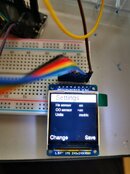
My ESP32 arrived and I had it setup on a breadboard along with a ADS1115, 2x buttons, a ST7789 1.54" 240*240 IPS LCD and all powered by a single 18650 battery. I also have got my ESP32 loaded up with the ST7789 display driver, so far so good up to this point.

Currently I have everything hooked up and preparing to request license and then hopefully I could start to download the codes into the ESP32 afterwards, but I couldn't get myself wrap around with the navigation with the buttons. I'm a Perdix user, and so i'm familiar with the 2 buttons operation - left button is Next and right button is like the enter button for confirmation.

Please allow me to break down the issues that i'm experiencing now:
  1. On the main screen where the Scubaboard logo is showing, the system will reboot each time I pressed down either one of the button. I can't get into the menu page, at all.
  2. To get into the menu from the main screen, I need to press down the Left button while I have to keep the Right button pressed down and hold. That way, I could get to see the menu scrolling from "Turn Off > Menu > Info > Main Screen". To get into one of the menu, while holding down the Right button, pressing the Left button to get to the menu I wish to get to, and then I have to Release & Hold the right button to select/enter/confirm.
  3. I couldn't save the setting I made at the setting page. I could get He Sensor toggled "On", but the system will freeze on me after I have toggled on the CO Sensor. Then I will have to cycle the power to restart the system, all settings done earlier is gone. The system will always freeze/crash when I play around with the CO Sensor toggle switch. I wonder if this is due to the absence of the sensors being connected onto the ADS1115?
IMG_20210608_104147.jpeg

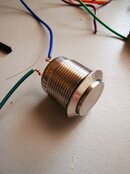
In regards with the navigational issue with my buttons, I have tried testing my buttons by swapping pin 26 & 27 around, I will still have keep the one button pressed in order to get the other to scroll the menus. FYI, the type of push button I use is as attached below, a 3V 2 prong steel push button, one pin connected to either pin 26/27, and the other one being connected to the + side of the breadboard.

IMG_20210608_140041.jpeg

So, what's your thought on these?

One last thing, I wonder if it is ok that I continue to communicate with you by sending emails to the email address as stated in the Info page? Thanks!

Regards,
CW
 
In regards with the navigational issue with my buttons, I have tried testing my buttons by swapping pin 26 & 27 around, I will still have keep the one button pressed in order to get the other to scroll the menus. FYI, the type of push button I use is as attached below, a 3V 2 prong steel push button, one pin connected to either pin 26/27, and the other one being connected to the + side of the breadboard.

believe other side of buttons should be connected to (ground) 0V not 3V
 
I wonder has anybody compared the He readings you get with the MD61/62 sensors to other analyzers?
In my case the results I get are not good.

I am measuring a blend that is supposed to be 19/32 (measured by a "professional" analyzer - sorry don't remember the type/brand) and with my device I get 19/40. My device is different than Miyaru's but the He reading is basically the same, i.e. get measurement, subtract any offset, divide by the maximum and multiply by 100 to get percent.

FYI I have tried priming the sensor as it is mentioned in the data sheet (left it on for hours to warm up vs minutes - there is not much difference within minutes of operation), I have calibrated it with 100% He (it gives me about 530mV output).

Since there is not much left to do I have abandoned the project (at least for now).
 
...
In regards with the navigational issue with my buttons, I have tried testing my buttons by swapping pin 26 & 27 around, I will still have keep the one button pressed in order to get the other to scroll the menus. FYI, the type of push button I use is as attached below, a 3V 2 prong steel push button, one pin connected to either pin 26/27, and the other one being connected to the + side of the breadboard.

View attachment 664054

So, what's your thought on these?

One last thing, I wonder if it is ok that I continue to communicate with you by sending emails to the email address as stated in the Info page? Thanks!

Regards,
CW
The action is performed on release of the button.
pressing a button = connecting pin 26/27 to HIGH.
releasing a button = connecting pin 26/27 to LOW.
You could connect a 10k resistor between pin26 and ground, also a 10k resistor between pin27 and ground and try if that works better with your buttons.
Maybe the buttons have a bounce time that exceeds the time I programmed.
believe other side of buttons should be connected to (ground) 0V not 3V
No, I decided to keep the input pins low, and use pushbuttons to make 'm high during a press.
That makes it possible to use capacitive touch buttons out-of-the-box, which by default send a low signal when not touched. Changing the operation requires a very delicate soldering job so I left that out.
 
No, I decided to keep the input pins low, and use pushbuttons to make 'm high during a press.
That makes it possible to use capacitive touch buttons out-of-the-box, which by default send a low signal when not touched. Changing the operation requires a very delicate soldering job so I left that out.

ahh, ok I was looking at the old schematic
 
I have calibrated it with 100% He (it gives me about 530mV output).

Curious knowing 100% = 530mV would you happen to know the mV reading you get at 0% and also at the 40% this would help determine whether me or hw or fw issue. Having 3 data points would be really useful.

You wouldn't happen to be using gain x8, that has a max input level of 512mV which may result in an error on the 100% calibration variable setting it too low
 
Curious knowing 100% = 530mV would you happen to know the mV reading you get at 0% and also at the 40% this would help determine whether me or hw or fw issue. Having 3 data points would be really useful.
In theory with air (0% He) I should get 0mV (by adjusting the variable resistor). In practice this value fluctuates a bit.
I have described what I see in a previous post but I am repeating it here:
upload_2020-11-3_11-0-5-png.622109.png

(at around 90minutes I had to move the circuit hence the small peaks you see).
That's the output I get over time with air (0% He) sensor being on my desk (away from my breath) in an air conditioned room (more or less stable room temperature). Since then I have readjusted the resistor so now after 20-30 minutes of operation I get values below 0.5mV or so which I consider as 0%.

I have done several He measurements at all these intervals (soon after I switch it on, 5 minutes later ie at the peak and half an hour later ie when it has reached the minimum) and this doesn't seem to affect much the output (I get results within 1-2% difference).

The problem is that with 32% He I get around 220mV instead of the expected (assuming the sensor is linear) 170mV, so it seems like the sensor isn't that linear (at least in my case).

You wouldn't happen to be using gain x8, that has a max input level of 512mV which may result in an error on the 100% calibration variable setting it too low
That's a good catch I haven't thought, but I am using x4 gain:
adc.setGain(GAIN_FOUR);

Anything else that might be going on here?

Thanks for the reply.
 
https://www.shearwater.com/products/teric/

Back
Top Bottom