A Honker? You can pick one up on eBay for $40 on a good day.

Why would you even want to? Well if you love vintage equipment, this one is a classic! And if you have feet-down trim problems, then all you need is 3 ½ lb of balancing brass up on the neck of your tank to help you get horizontal! Perhaps you’re a distracted photographer, who can make use of what this regulator was designed for: a warning “honk” when you reach anything from 200-400 psi tank pressure, from the days when SPG’s were rare.
The problem is, this reg is no longer serviced by Scubapro. Many parts are no longer available. And all that’s out there on Frogkick and other schematic websites is a parts breakdown.
This thread will lead you through the Mark VII in detail, dispelling old wives’ tales, explaining how it works, along with how to service it, how to restore it, and where you can source parts that are close enough to original specification to enable creation of a demonstration regulator that is within the original manufacturer's specification. Where other ScubaBoarders chime in with valuable info, I’ll update the thread to include or correct information.
The Scubapro Mark VII “Honker” is a follow-on to the venerable Mark V balanced piston first stage regulator. It was introduced around 1971 and went through multiple iterations for over 25 years until at least December, 1997, when Schematic Revision "S" appeared. This regulator was essentially a Mark V coupled with a “sonic oscillator” that used an unstable brass cylinder and low tank pressure air flow to vibrate against the reg body, producing an audible “honk” that could be heard for a significant distance underwater when tank pressures dropped below 250-400 psi. Even though SPG’s were available at the time, the regulator continued to sell as a "safety feature". Indeed, a 1978 warning advised owners not to rely on the "honk" but to utilize an SPG.
The Mark V regulator design inside the Mk VII continues to be one of the best performing balanced regulators out there. Its large piston head resulted in brisk lockup, and only the invention of the blunt-nose piston for the cone seat of the Mk10 regulator (which became the Mk10+) ended its reign. With the smaller piston head of the Mk10+ however, lockup was occasionally problematic, and the Mk 5 and Mk 7 continued in regular use until large-head pistons returned with the Mk20, and then Mk25 series (still in production today).
The Mark VII body had at least three iterations, including an early move from a 2475 psi yoke with the same 3/8-24 threading in each of the yoke, LP port and HP port, to a 7/16-20 threaded yoke rated to 3000 psi (???), and finally a heavy yoke with a 9/16” thread wing nut eventually succeeded by the familiar knob style used in other Scubapro regulators.
The first and third iterations are pictured below:

Interestingly, the Revision Q schematic from September, 1989 shows all four yoke knobs together with a heavy yoke body and 3000 psi specification. No warning is given regarding earlier models with 2475 psi yokes. The 1994 schematic includes a note specifying that only the 9/16” knob and yoke is rated to 3000 psi, while 3/8” and 7/16” are limited to 2475. In contrast, a schematic from 1976 (Revision C) erroneously shows a thin legged yoke with 3000 psi stamped on the body, with a 7/16” winged yoke screw. The 1994 schematic superceded this apparent error.
Ambient pressure ports into the regulator began with three holes, although as early as 1984 they were replaced by two SPEC-style dimples with five tiny perforations in each dimple, to better retain silicone grease. This persisted to 1997 in Revision S. See second picture above.
The Honker never had more than two LP ports and one HP port, but eBay Honkers typically come with a variety of port multipliers or tees.

From the outside, here is the component breakdown:
On the end with the single 3/8” or 7/16” HP port in the center, we see the high pressure compartment of the Mk5 regulator on the left. The high pressure port was changed from 3/8” to 7/16” according to a 1988 schematic, although it probably occurred much earlier. On the right, a large unvented cap with an o-ring seals a low pressure compartment that contains the oscillator assembly.

The HP seat carrier originally held a flat seat, though it will also accommodate any of the Mk10 cone seats.

On the other end, we see two LP ports, with a flat head screw fitting in between.

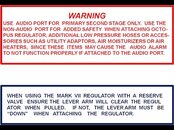
The left hand port is machined directly into the body, and you should see “AUDIO” stamped alongside. This port is the outflow of the oscillator chamber, and should always be where the primary second stage is plugged in. The LP port on the right is in the center of a large pin spanner cap, which covers the Mk5 piston head. This is a “high flow” port, coming straight off the base of the piston. However, using it will bypass the oscillator safety feature. It can be considered for either an octo, a BCD inflator hose, or both as a tee was commonly mounted here.

Between the two ports is a small plug with an adjustment slot for a flat-bladed screwdriver. This plug is sealed by an o-ring, and although the o-ring specified appears to be a duro 70 seal, it should be noted that this plug seals a HP mechanism used to fix the final position of the oscillator. This will be discussed further below. The safe range of adjustment is probably less than one full turn of the plug. For reasons discussed below, it is probably safest to leave the plug fully screwed in, if you can get a honk with that setting. Additional recommended modifications will also be covered later.
The tank mount is a standard yoke fitting, of either 2475 psi or 3000 psi rating. The rating is quickly distinguished by the thickness of the yoke. The tank screw went through three iterations, from a 3/8-24 to a 7/16-20 to the current 9/16-18 thread size. The inlet is protected by a sintered metal filter below a star retainer, and the flat filter used earlier rests on an o-ring, while later versions were bored to accept the more common conical filter currently used in the Mk25, without an oring spacer.

The sheer size of the reg body (it weighs 3lb 7oz!) also caused a change in the handle of the then-popular J-valve, which was too long to slide past the regulator when a diver attempted to pull it into the “reserve” position.

That problem prompted the required addition of one of two warning decals.
This one read:
Finding a Honker with intact decals is a rare find indeed!

Two to three ambient pressure holes in the body are found on the regulator side (the left side when viewed from the HP port end; or the right side when viewed from the LP outlets). See the second photo above.
Let’s now look at the internals in more detail.
(continued in next post)
Why would you even want to? Well if you love vintage equipment, this one is a classic! And if you have feet-down trim problems, then all you need is 3 ½ lb of balancing brass up on the neck of your tank to help you get horizontal!
Perhaps you’re a distracted photographer, who can make use of what this regulator was designed for: a warning “honk” when you reach anything from 200-400 psi tank pressure, from the days when SPG’s were rare.The problem is, this reg is no longer serviced by Scubapro. Many parts are no longer available. And all that’s out there on Frogkick and other schematic websites is a parts breakdown.
This thread will lead you through the Mark VII in detail, dispelling old wives’ tales, explaining how it works, along with how to service it, how to restore it, and where you can source parts that are close enough to original specification to enable creation of a demonstration regulator that is within the original manufacturer's specification. Where other ScubaBoarders chime in with valuable info, I’ll update the thread to include or correct information.
DISCLAIMER: Restoring a “no longer supported” regulator is a risky endeavor that should not be used to prepare an old specimen for your actual use in the water, much less to give to a friend. This procedure is designed for preparation of a mantle-top specimen about which you can brag to your friends,
“This antique could actually be used!”, even if you shouldn’t.
‘Nuff said.
“This antique could actually be used!”, even if you shouldn’t.
‘Nuff said.
The Scubapro Mark VII “Honker” is a follow-on to the venerable Mark V balanced piston first stage regulator. It was introduced around 1971 and went through multiple iterations for over 25 years until at least December, 1997, when Schematic Revision "S" appeared. This regulator was essentially a Mark V coupled with a “sonic oscillator” that used an unstable brass cylinder and low tank pressure air flow to vibrate against the reg body, producing an audible “honk” that could be heard for a significant distance underwater when tank pressures dropped below 250-400 psi. Even though SPG’s were available at the time, the regulator continued to sell as a "safety feature". Indeed, a 1978 warning advised owners not to rely on the "honk" but to utilize an SPG.
The Mark V regulator design inside the Mk VII continues to be one of the best performing balanced regulators out there. Its large piston head resulted in brisk lockup, and only the invention of the blunt-nose piston for the cone seat of the Mk10 regulator (which became the Mk10+) ended its reign. With the smaller piston head of the Mk10+ however, lockup was occasionally problematic, and the Mk 5 and Mk 7 continued in regular use until large-head pistons returned with the Mk20, and then Mk25 series (still in production today).
The Mark VII body had at least three iterations, including an early move from a 2475 psi yoke with the same 3/8-24 threading in each of the yoke, LP port and HP port, to a 7/16-20 threaded yoke rated to 3000 psi (???), and finally a heavy yoke with a 9/16” thread wing nut eventually succeeded by the familiar knob style used in other Scubapro regulators.
The first and third iterations are pictured below:
Interestingly, the Revision Q schematic from September, 1989 shows all four yoke knobs together with a heavy yoke body and 3000 psi specification. No warning is given regarding earlier models with 2475 psi yokes. The 1994 schematic includes a note specifying that only the 9/16” knob and yoke is rated to 3000 psi, while 3/8” and 7/16” are limited to 2475. In contrast, a schematic from 1976 (Revision C) erroneously shows a thin legged yoke with 3000 psi stamped on the body, with a 7/16” winged yoke screw. The 1994 schematic superceded this apparent error.
Ambient pressure ports into the regulator began with three holes, although as early as 1984 they were replaced by two SPEC-style dimples with five tiny perforations in each dimple, to better retain silicone grease. This persisted to 1997 in Revision S. See second picture above.
The Honker never had more than two LP ports and one HP port, but eBay Honkers typically come with a variety of port multipliers or tees.
From the outside, here is the component breakdown:
On the end with the single 3/8” or 7/16” HP port in the center, we see the high pressure compartment of the Mk5 regulator on the left. The high pressure port was changed from 3/8” to 7/16” according to a 1988 schematic, although it probably occurred much earlier. On the right, a large unvented cap with an o-ring seals a low pressure compartment that contains the oscillator assembly.
The HP seat carrier originally held a flat seat, though it will also accommodate any of the Mk10 cone seats.
On the other end, we see two LP ports, with a flat head screw fitting in between.
The left hand port is machined directly into the body, and you should see “AUDIO” stamped alongside. This port is the outflow of the oscillator chamber, and should always be where the primary second stage is plugged in. The LP port on the right is in the center of a large pin spanner cap, which covers the Mk5 piston head. This is a “high flow” port, coming straight off the base of the piston. However, using it will bypass the oscillator safety feature. It can be considered for either an octo, a BCD inflator hose, or both as a tee was commonly mounted here.
Between the two ports is a small plug with an adjustment slot for a flat-bladed screwdriver. This plug is sealed by an o-ring, and although the o-ring specified appears to be a duro 70 seal, it should be noted that this plug seals a HP mechanism used to fix the final position of the oscillator. This will be discussed further below. The safe range of adjustment is probably less than one full turn of the plug. For reasons discussed below, it is probably safest to leave the plug fully screwed in, if you can get a honk with that setting. Additional recommended modifications will also be covered later.
The tank mount is a standard yoke fitting, of either 2475 psi or 3000 psi rating. The rating is quickly distinguished by the thickness of the yoke. The tank screw went through three iterations, from a 3/8-24 to a 7/16-20 to the current 9/16-18 thread size. The inlet is protected by a sintered metal filter below a star retainer, and the flat filter used earlier rests on an o-ring, while later versions were bored to accept the more common conical filter currently used in the Mk25, without an oring spacer.
The sheer size of the reg body (it weighs 3lb 7oz!) also caused a change in the handle of the then-popular J-valve, which was too long to slide past the regulator when a diver attempted to pull it into the “reserve” position.
That problem prompted the required addition of one of two warning decals.
This one read:
WHEN USING THE MARK VII REGULATOR ON A RESERVE VALVE,
BE SURE THE LEVER ARM WILL CLEAR THE REGULATOR WHEN PULLED.
IF NOT, THE LEVER ARM MUST BE "DOWN" WHEN ATTACHING A REGULATOR.
BE SURE THE LEVER ARM WILL CLEAR THE REGULATOR WHEN PULLED.
IF NOT, THE LEVER ARM MUST BE "DOWN" WHEN ATTACHING A REGULATOR.
Finding a Honker with intact decals is a rare find indeed!
Two to three ambient pressure holes in the body are found on the regulator side (the left side when viewed from the HP port end; or the right side when viewed from the LP outlets). See the second photo above.
Let’s now look at the internals in more detail.
(continued in next post)