Project Argonaut, totally new, vintage style DH regulator

Please register or login

Welcome to ScubaBoard, the world's largest scuba diving community. Registration is not required to read the forums, but we encourage you to join. Joining has its benefits and enables you to participate in the discussions.

Benefits of registering include

  • Ability to post and comment on topics and discussions.
  • A Free photo gallery to share your dive photos with the world.
  • You can make this box go away

Joining is quick and easy. Log in or Register now!

The Venturi action from the HPR and the plastic cans is powerful and smooth and easily controlled. The HPR valve is adjustable in that the two side Venturi can be blocked or partially blocked to tune the Venturi assist to the diver's preference. The plastic case, changing nothing else, the Venturi assist is noticeably better, though not hugely so, when compared to the metal cans.

There were double hose regulators with mushroom exhaust valves. As with other regs of that ancient age of yore, the valves were small, stiff and thick neoprene affairs and were hard to exhale through. The thought in that era was that inhalation effort was the primary concern. Of course it is important, breaking force and Venturi flow for a low WOB, but it has been shown that exhalation effort is just as important if not more so. There are no double hose regulators, including even the vaunted Phoenix HPR RAM, that can take the Argonaut Kraken to the mat. And if an AL Mentor ever shows up in the flesh, it better have it's game face on and be prepared for a axx wuppin.

N
 
Setting up an Argonaut Kraken.
26012f295e72470edd51c6025ca6deed.jpg


Sent from my GT-I9500 using Tapatalk
 
I like the color of that lever.


I also like this picture. It shows the captive hardware.
I do not like loose hardware. IMO: loose hardware = lost hardware.


attachment.php


---------- Post added June 5th, 2015 at 11:26 PM ----------

Such a simple, elegant solution. Wonder why the old double hose reg designers didn't think of this. (But I still think a chromed brass can is sexier.)

I also like the looks of chrome brass, but there is no way to design the complex curves and geometry that I needed in a metal can (not even a metal casting, never mind the weight). I am not even talking about the cost. The advantages in geometry design and light weight of this material, made it the ideal choice.
 
I agree with Luis on this; the plastic cans have a huge advantage over the metal cans. Not only can they be formed into about any shape, but they also are impervious to corrosion. rx7diver asks "...why the old double hose reg designers didn't think of this." Actually, they did, but the old-time divers did not accept these plastic regulators. They did not think the plastic was robust enough. But look at an old Jet Air by USD, or the AMF Voit plastic Fifty Fathom, and their cans today are in about the same condition as when they were manufactured. You cannot say that about chromed brass. I have a number of plastic regulators, single hose regs such as the Sherwood second stage, and it's still in pristine condition after thirty years. The same will happen with the Argonaut Kraken--in thirty years it will continue to provide the same performance it does today, and the cans will still look beautiful.

SeaRat

---------- Post added June 6th, 2015 at 02:09 PM ----------

I just dove my White Stag DEEP 1 regulator, with plastic second stages from the 1970s. They work as well today as they did when new.

John
 
The exhaust effort, measured on my bench, surface conditions, is among the lowest I have measured of any type regulator. Once the loop is submerged in a typical swimming position the exhaust effort is extremely low.

N

Hi Nemrod
I published some exhaust flow resistance test data. The data was taken using scientific methodology, were I did a true side by side comparison of different exhaust types. I controlled all the variables to make a true comparison (not an “apples to oranges” type comparison). I also did simulated deep water testing using non-dimensional Reynolds number scaling to predict the flow resistance encountered by the density change (equivalent to 5 atmospheres).

Some of the data can be found in this link:
Vintage Double Hose

And as expected, I always do a proper error analysis (when collecting data). Analyzing and evaluating the potential data inaccuracies and potential errors is extremely important to determine if the data is worth anything. Data verification and validation is as important as having the data.

My instrumentation was calibrated or verified. I have calibrated analog and digital gauges that are very accurate.

In my recent post about flow rates, that is just a gross observation, not actual scientific data. I actually have accurate volume data for those tanks (measured using precise water weight/ volume), but for this purpose I just presented some rough numbers.

Another example of inaccurate data is how we talk about the steel 72 as having 71.2cuft. The manufacturers showed three significant digits probably for advertising, to give the illusion of precision. In science and engineering we considered that misleading (could even be considered unethical if done intentionally).

I have measured the actual volume of a dozen different steel 72 (using water) They range from 69.6 to 72.2. The average was 70.6 cu ft. Notice in this case I actually used three significant digits. Every measurement was held to at least that accuracy.

When I talk about a steel 72, I normally say that it hold about 71 cu ft, at about 2500 psi.

Note: This thread is about the Argonaut and its related development from its vintage roots to a truly modern regulator. This thread is not about steel 72 or about other regulators, plastic or otherwise.
I only mentioned the steel 72 as an example of the process I follow to try to get accurate engineering data, during the development of the Argonaut and other projects. The accuracy is limited by my resources, but I did followed well established scientific principles as closely as possible.
Thanks


---------- Post added June 8th, 2015 at 07:01 AM ----------


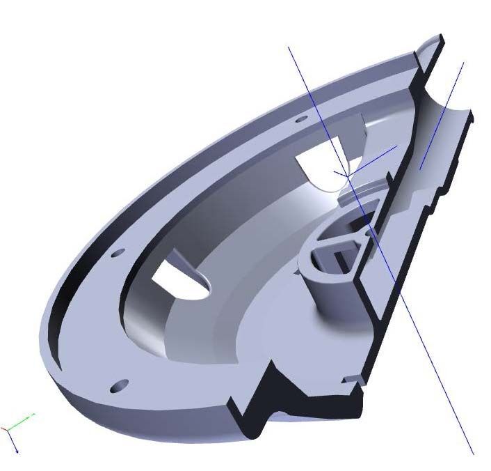
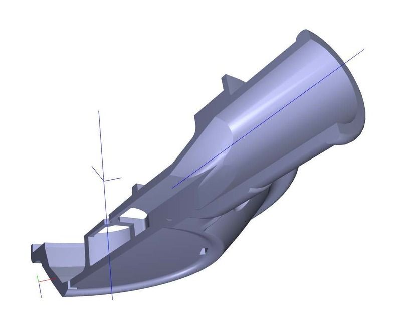
Below are two cross-section shots of the exhaust can 3D model.

A huge advantage of this fabrication/ molding process is that it allow me to design the can with thicker material cross section in any of the higher stressed areas. Notice that all the sharp inside corners have a generous radius and the changes in material thickness. It was easy to add reinforcing material were needed.


cut%20picute%20of%20exhaust%20can_zps0lk2orzb.jpg


It was also easy to design a smooth round to square transition for the exhaust duct-work. Notice the exhaust flow path.

I worked (as a design engineer) for almost ten years in industrial gas flow control equipment. A metal duct could never be fabricated with such a smooth transition, it doesn’t matter if it is this small or 10 feet in diameter.


can%20cut_zps32wjv1rt.jpg


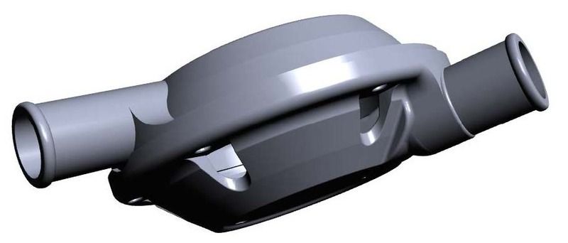
Notice the reinforcements were the horns transition into the cans. You can see the details from the model in the actual parts.

Note: the length of the two horns is exactly the same. I just notice that the perspective view on this shot makes them look like if they had different length.

can%20model_zpsrn4bozny.jpg
 
Luis,

It might be useful if you give a little explanation, for the troops, of how the Kraken HPR valve can be tuned to increase or decrease Venturi effect irrespective of cracking force settings.

N
 
I published some exhaust flow resistance test data. The data was taken using scientific methodology, were I did a true side by side comparison of different exhaust types. I controlled all the variables to make a true comparison (not an “apples to oranges” type comparison). ... And as expected, I always do a proper error analysis (when collecting data). Analyzing and evaluating the potential data inaccuracies and potential errors is extremely important to determine if the data is worth anything. Data verification and validation is as important as having the data.

My instrumentation was calibrated or verified. I have calibrated analog and digital gauges that are very accurate.


Commendable approach to experimental data collection and analysis.

Safe diving,

rx7diver
 
Last edited:
Luis,

you might explain why the Argonaunt's exhaust is designed with that ridge just outside the mushroom valve. My tests on the Healthways SCUBA Delux years ago showed that this is very necessary, but I think your explanation would be better for prospective buyers to hear.

SeaRat
 
The DBE..(Duckbill Eliminator) rapid prototype shown, came first. The Argonaut exhaust can design maximizes the potential of this idea. The raised ridge area is there to prevent contact between the exhaust valve and the main diaphragm. The DBE is limited in its potential by the original can geometry but eliminates the maintenance and mess of the original duckbill exhaust design. The Argonaut is superior all the way around in this aspect.
DSC07346.jpgDSC07351.jpgDSC07354.jpgDSC07355.jpgDSC07356.jpg
 
I would like to add that during the normal breathing cycle, the diaphragm normally would not touch the exhaust valve (even without the stop). There is not a lot of extra clearance, but I did design sufficient clearance for normal operation.

The stop is really only needed if the diaphragm extends out a bit. This would normally only happen, for example, with a hard exhalation if there is a little leak in the inlet mouthpiece valve. The new mushroom valve rarely leak, but occasionally they may momentarily leak a little bit.


Looking at the old 3D printed duckbill is a good reminder of how some of the components have evolved and come together into the design of the Argonaut. This didn’t happen overnight. I will try to write more about this subject when I have some time.
 
Last edited:
https://www.shearwater.com/products/swift/

Back
Top Bottom