tmassey
Contributor
TL;DR: the Blue Steel 7/8" UNF manifold currently being sold by Piranha Dive Mfg does *not* fit on 3500 PSI Genesis / PST tanks without significant machining of the valves! Read below for the nitty-gritty details, but unless you're comfortable machining the brass of your valves, be *very* careful before you buy this manifold. Below I outline the process I used to grind down the o-ring land to allow the valve to fit.
I recently picked up some PST HP120 true-3500 PSI steel tanks with the narrow necks cheap. (Thanks @Tracy !). The official name for those threads are 7/8" UNF. These are not the standard, wider (3/4" NPS) tank necks. The tanks were configured as single tanks, and I want them as manifolded doubles.
Until recently, there were few options for doubling these tanks -- and all of them sucked. However, Piranha Dive Mfg. has recently started selling Blue Steel manifolds for these tanks with all of the features of a modern manifold: radially-sealed isolation crossbar (with 3 o-rings) with 215mm spacing that supports standard high-gauge 7-1/4" tank bands, and at a reasonable price. The only used HP120 tanks I have been able to find are all 7/8" tanks. I had previoulsy sworn off the narrow-neck tanks because of the miserable manifold, but with the availability of a new, modern manifold for the narrow tanks, I decided to take the plunge.
When I installed the new valves, I found that there was a roughly 1/8" gap between the bottom of the valve and the top of the tank, but the valves were not able to screw on any farther. You could see the o-ring filling the gap. This did not seem right, but I couldn't do anything about it, so I went on to complete assembling the doubles. I then went to fill them, and an o-ring extruded, releasing the gas. OK, then: I tore everything apart again and replaced both neck o-rings, this time with 90-duro. Reassembled everything again, and started a fill. This time, *both* o-rings extruded!
OK, so something is clearly wrong. I then closely compared the Blue Steel valves with the valves that came off the tank.
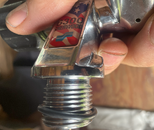
Here's a photo of the neck of the original valve:
(All images are thumbnails: click to see a larger version.)
Notice the area above the threads: the o-ring land. There is clearly a bit of a groove above the threads.
And now here's the Blue Steel valve:
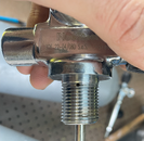
It's neck is exactly the opposite: there is a healthy shoulder of brass above the threads. And sure enough: the valves will only tighten until that shoulder hits the top of the tank. The o-ring stays mostly outside of the tank lip, and when the pressure gets high enough (something like only 1000 PSI), the o-ring blows out.
So, it's clear that that shoulder isn't supposed to be there... So what do we do about it? My options were slim: I don't want the old-style manifolds, and the only modern manifold I can get is the Blue Steel. So we're going to need to make the Blue Steel work by removing that extra material.
One problem: I don't own a lathe, and I wouldn't know how to use it if I did... So what can I do instead? How about using a drill to spin the valve, and a file to remove the material. So after some brainstorming, that's what I did.
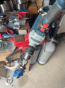
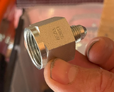
First I bought an adapter fitting: 7/8" UNF-F to JIC-4. In fact, I bought this one. This allowed me to screw the valve into one side, and put the other side into the chuck of a 5/8" drill. I then used a vise to grip the stabilization handle of the drill. I used a hose clamp around the trigger to give me a relatively slow, consistent rotation, and plugged the drill into a strip so I could use its switch to turn my makeshift lathe on and off. I initially started with a quite slow speed, but ended up increasing it to something in the neighborhood of 200 or so RPM.
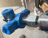
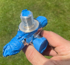
I removed the dip tube and valve wheel. I then taped up the valve with 3M Blue masking tape: all the openings, as well as the flat bottom of the valve. The idea was to try to save the chrome on the bottom of the valve. I shingled the tape on the bottom to try to keep it stuck on the valve, but with only limited success. I also tried 3M Heavy Duty shipping tape (clear packing tape), but it wouldn't stick to the valve well at all. I thought about using Gorilla Tape (which is like heavy-duty duct tape), but I ended up not.
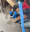
I then pulled out a bunch of files to see what might work. I started with some smaller 6" files, but in the end they were too narrow. 12" files ended up being the right thickness: I would recommend simply using those. I only used the thin edge of the file. I also applied masking tape to the broad sides of the file, again trying to save the chrome on the bottom of the valve. Here's what that looked like:
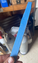
The right edge of the file is bare of tape, and that is the edge I used, placed against the shoulder as it rotated in the drill.
I actually started with a hacksaw with a fine-tooth metal blade, again taped on the sides. I found that this worked well to get the brass right up against the bottom of the valve without chewing up the bottom of the valve. But be careful: it can cut deeply and quickly. Make sure you don't go too deep with it!
Speaking of that, how deep do you need to go? I used a cheap digital caliper on the original valve to find that the o-ring land was 19.5mm. The Blue Steel shoulder was 23 or so mm. So I needed to remove 2mm or so of material: which certainly felt like a lot! I took my time and checked my depth frequently and eventually worked down to the right depth. I would start with the hacksaw to create a groove right up against the valve base, then use the file to get down to the same level, back and forth until I got down to 19.5mm.
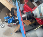
I then taped a piece of 200-grit sandpaper to the bottom edge of the file and used that to smooth the machined area. The edge of the sandpaper is right at the right edge of of the bottom, such that it will only sand the *bottom* of the land, not the side (the part that's shared with the base of the valve), again in an attempt to save the chrome on the bottom. I wasn't worried about polishing it, just getting it smooth and a bit shiny.
Wow, a time I *didn't* hit the 10,000 character limit -- but I hit the 5-photo limit... So, on to the next post.
I recently picked up some PST HP120 true-3500 PSI steel tanks with the narrow necks cheap. (Thanks @Tracy !). The official name for those threads are 7/8" UNF. These are not the standard, wider (3/4" NPS) tank necks. The tanks were configured as single tanks, and I want them as manifolded doubles.
Until recently, there were few options for doubling these tanks -- and all of them sucked. However, Piranha Dive Mfg. has recently started selling Blue Steel manifolds for these tanks with all of the features of a modern manifold: radially-sealed isolation crossbar (with 3 o-rings) with 215mm spacing that supports standard high-gauge 7-1/4" tank bands, and at a reasonable price. The only used HP120 tanks I have been able to find are all 7/8" tanks. I had previoulsy sworn off the narrow-neck tanks because of the miserable manifold, but with the availability of a new, modern manifold for the narrow tanks, I decided to take the plunge.
When I installed the new valves, I found that there was a roughly 1/8" gap between the bottom of the valve and the top of the tank, but the valves were not able to screw on any farther. You could see the o-ring filling the gap. This did not seem right, but I couldn't do anything about it, so I went on to complete assembling the doubles. I then went to fill them, and an o-ring extruded, releasing the gas. OK, then: I tore everything apart again and replaced both neck o-rings, this time with 90-duro. Reassembled everything again, and started a fill. This time, *both* o-rings extruded!
OK, so something is clearly wrong. I then closely compared the Blue Steel valves with the valves that came off the tank.
Here's a photo of the neck of the original valve:

(All images are thumbnails: click to see a larger version.)
Notice the area above the threads: the o-ring land. There is clearly a bit of a groove above the threads.
And now here's the Blue Steel valve:

It's neck is exactly the opposite: there is a healthy shoulder of brass above the threads. And sure enough: the valves will only tighten until that shoulder hits the top of the tank. The o-ring stays mostly outside of the tank lip, and when the pressure gets high enough (something like only 1000 PSI), the o-ring blows out.
So, it's clear that that shoulder isn't supposed to be there... So what do we do about it? My options were slim: I don't want the old-style manifolds, and the only modern manifold I can get is the Blue Steel. So we're going to need to make the Blue Steel work by removing that extra material.
One problem: I don't own a lathe, and I wouldn't know how to use it if I did... So what can I do instead? How about using a drill to spin the valve, and a file to remove the material. So after some brainstorming, that's what I did.
First I bought an adapter fitting: 7/8" UNF-F to JIC-4. In fact, I bought this one. This allowed me to screw the valve into one side, and put the other side into the chuck of a 5/8" drill. I then used a vise to grip the stabilization handle of the drill. I used a hose clamp around the trigger to give me a relatively slow, consistent rotation, and plugged the drill into a strip so I could use its switch to turn my makeshift lathe on and off. I initially started with a quite slow speed, but ended up increasing it to something in the neighborhood of 200 or so RPM.

I removed the dip tube and valve wheel. I then taped up the valve with 3M Blue masking tape: all the openings, as well as the flat bottom of the valve. The idea was to try to save the chrome on the bottom of the valve. I shingled the tape on the bottom to try to keep it stuck on the valve, but with only limited success. I also tried 3M Heavy Duty shipping tape (clear packing tape), but it wouldn't stick to the valve well at all. I thought about using Gorilla Tape (which is like heavy-duty duct tape), but I ended up not.
I then pulled out a bunch of files to see what might work. I started with some smaller 6" files, but in the end they were too narrow. 12" files ended up being the right thickness: I would recommend simply using those. I only used the thin edge of the file. I also applied masking tape to the broad sides of the file, again trying to save the chrome on the bottom of the valve. Here's what that looked like:

The right edge of the file is bare of tape, and that is the edge I used, placed against the shoulder as it rotated in the drill.
I actually started with a hacksaw with a fine-tooth metal blade, again taped on the sides. I found that this worked well to get the brass right up against the bottom of the valve without chewing up the bottom of the valve. But be careful: it can cut deeply and quickly. Make sure you don't go too deep with it!
Speaking of that, how deep do you need to go? I used a cheap digital caliper on the original valve to find that the o-ring land was 19.5mm. The Blue Steel shoulder was 23 or so mm. So I needed to remove 2mm or so of material: which certainly felt like a lot! I took my time and checked my depth frequently and eventually worked down to the right depth. I would start with the hacksaw to create a groove right up against the valve base, then use the file to get down to the same level, back and forth until I got down to 19.5mm.

I then taped a piece of 200-grit sandpaper to the bottom edge of the file and used that to smooth the machined area. The edge of the sandpaper is right at the right edge of of the bottom, such that it will only sand the *bottom* of the land, not the side (the part that's shared with the base of the valve), again in an attempt to save the chrome on the bottom. I wasn't worried about polishing it, just getting it smooth and a bit shiny.
Wow, a time I *didn't* hit the 10,000 character limit -- but I hit the 5-photo limit... So, on to the next post.


