Titanic tourist sub goes missing sparking search

Please register or login

Welcome to ScubaBoard, the world's largest scuba diving community. Registration is not required to read the forums, but we encourage you to join. Joining has its benefits and enables you to participate in the discussions.

Benefits of registering include

  • Ability to post and comment on topics and discussions.
  • A Free photo gallery to share your dive photos with the world.
  • You can make this box go away

Joining is quick and easy. Log in or Register now!

In the old days (mid 1960 & 70s), most saturation and deep-bounce diving bells were rated for internal and external pressure. I was always MUCH more nervous on one atmosphere/external pressure dives.

The idea was that divers could inspect the worksite at one atmosphere, get geared up, and do a rapid blow down (pressurize) to working depth. ROVs have eliminated that need and saturation has displaced deep mixed gas bounce dives.
 
Indeed, it’s beyond reckless. Those “fireworks” are the sound of the carbon fiber delaminating (breaking up), which is way beyond the yield strength of the material. A safe operation of the material under pressure cycles should be done within the modulus of resilience of the material, the linear zone of stress-strain curve of the material, O to A zone, in the Chicago Cuve figure, below.

View attachment 790484
Courtesy of Exploring the Stress / Strain Curve for Mild Steel - The Chicago Curve

The maximum allowable working pressure (MAWP) should be at 2/3 of the test pressure. That means if the test is done at 4000 m depth, the MAWP is at 2,667 m depth. If MAWP is at 4000 m depth, you need to test it to 6000 m depth. The test pressure should be under the yield strength (point A in the figure, above), within the modulus of resilience. Those “fireworks” occur at point E in the figure, above. Nuts!

Increasing the MAWP can be done by material thickness and structure (sphere is stronger than cylinder, flat plate being the weakest).
I am starting to wonder if it broke longitudinally.
The center of the cyl was bucking inward compared to the ends and breaking the strand side by side,

I still think if he had a bulkhead, in the middle it would have been alot better, or build a reverse tank, carbon fiber and epoxy a 1/4ish ring of titanium over top of it,

But the whole thing seems flawed from the beginning.

Longitudinally meaning the straight part of the cylinder? I would think that would be the weakest part of the cylindrical structure. It would be better to make it into oval (like an egg) if spherical is not desirable in terms of maximizing internal cavity for passenger room.
 
I still think if he had a bulkhead, in the middle it would have been alot better, or build a reverse tank, carbon fiber and epoxy a 1/4ish ring of titanium over top of it,

Not sure if I understand what you mean. May be you can draw it up & post the drawing here?

When mixing the materials such as carbon fibers, epoxy and metal (titanium) we need to know the effect of pressure on the material contraction and how much difference their values relative to each other as that would affect the sealing tolerance and we are dealing with high pressure environment (6000 psig) and pessure cycling the materials from 0 to 6000 psig.
 
Indeed, it’s beyond reckless. Those “fireworks” are the sound of the carbon fiber delaminating (breaking up), which is way beyond the yield strength of the material. What I learned in my sophomore year of Materials Science & Engineering in University of California at Berkeley, a safe operation of the material under pressure cycles should be done within the modulus of resilience of the material, the linear zone of stress-strain curve of the material, O to A zone, in the Chicago Cuve figure, below.

View attachment 790484
Courtesy of Exploring the Stress / Strain Curve for Mild Steel - The Chicago Curve

The maximum allowable working pressure (MAWP) should be at 2/3 of the test pressure. That means if the test is done at 4000 m depth, the MAWP is at 2,667 m depth. If MAWP is at 4000 m depth, you need to test it to 6000 m depth. The test pressure should be under the yield strength (point A in the figure, above), within the modulus of resilience. Those “fireworks” occur at point E in the figure, above. Nuts!

Increasing the MAWP can be done by material thickness and structure (sphere is stronger than cylinder, flat plate being the weakest).
That is the curve and numbers for steel. Other materials are different, perhaps quite different.
 
That is the curve and numbers for steel. Other materials are different, perhaps quite different.

Of course. It’s just an illustration. Notice that there’s no numbers and units given in the axis.
 
Of course. It’s just an illustration. Notice that there’s no numbers and units given in the axis.
The numbers are in your text.
 
The numbers are in your text.

What numbers in my text?

I mentioned if you want to have MAWP of 4000 m depth, you need to test it at 6000 m depth.

Here is for different material. The modulus of resilience is there, but at lower range than that of steel. The point that I try to make is if you want to operate the submersible using such material, you need to test it within the modulus of resilience of the material.

IMG_1711.jpeg

Courtesy of https://www.researchgate.net/figure...lone-dotted-line-and-reinforced_fig2_41014868
 
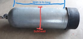
If you think of it 2 dimensionally,
As a I beam or tubing, as long as it stays apart it can span along way,
The way it looks wrapped, it strong in a cylinder way, but not the long way.

A bulk head is a way to fix the existing design,
Not really what you want to do...

Not sure if all carbon fiber tanks have a thin a steel liner inside, but then the fiber gets wound around it, it becomes strong,

My thought is to build that in reverse,,,
Seems like a technical challenge, that might not work well,
 

Attachments

  • 20230701_135937.jpg
    20230701_135937.jpg
    35.8 KB · Views: 53
Great tragedy.
Not like anyone needed more reason to stay away from CFRP underwater. Excellent material, just not for that load profile.

I used to work at a company that built deep submersibles. Steel, titanium and aluminum, with titanium performing the best. The reason is, the least hidden problems - bad welds are detectable, everything else lasts once it's done.(Made some minor dive gear out of the scraps as well).

Composites and mixed materials are unpredictable due to differing rates of compression and expansion, including inside the material, possible galvanic corrosion (CFRP participates in it) if some barrier coatings are broken, and the ability of seawater to seep into any crack. Hull penetrations are where long-term leaks tend to arise, even if it's just slightly different grades of alloy steel. Collapse-level problems are probably due to internal delamination, though.

Another promising underwater material is reactive powder concrete, but it will need lots of testing and experience in unmanned applications first, before going to manned use at really high load factors.
 
Back
Top Bottom