
It's not common to try and transmit anything at 38KHz, like madUK said you could base this off an IR library cause it uses 38KHz also, for the antenna, there is a lot of math and science to calculate the correct number of windings, shape and whatnot, i dont know any of it so I just say a lot. If you have an old speaker you could cut the diaphragm out and use the coil that's attached to it. Or just take some coated speaker wire and wind it around something a bunch of times. Needs to be enough that you dont burn out the arduino, for a finished "product" I'll do some searching to find what would be a good choice.I have been looking around and it looks like there is absolutely no project even attempting to do RF transmission at 38 kHz or even LF.
I wanted to try have fun with the few arduinos I own. But I'm stuck at the antenna part. I can't find something that would work.
You seem to mention a coil and ferrite. How big/long the coil? How many winds?

You are using an out of date browser. It may not display this or other websites correctly.
You should upgrade or use an alternative browser.
You should upgrade or use an alternative browser.
Reading Wireless Air Transmitter using Arduino
- Thread starter Nickorossa
- Start date
Please register or login

Welcome to ScubaBoard, the world's largest scuba diving community. Registration is not required to read the forums, but we encourage you to join. Joining has its benefits and enables you to participate in the discussions.
Benefits of registering include
- Ability to post and comment on topics and discussions.
- A Free photo gallery to share your dive photos with the world.
- You can make this box go away
MadUKDiver
Registered
It's not common to try and transmit anything at 38KHz, like madUK said you could base this off an IR library cause it uses 38KHz also, for the antenna, there is a lot of math and science to calculate the correct number of windings, shape and whatnot, i dont know any of it so I just say a lot. If you have an old speaker you could cut the diaphragm out and use the coil that's attached to it. Or just take some coated speaker wire and wind it around something a bunch of times. Needs to be enough that you dont burn out the arduino, for a finished "product" I'll do some searching to find what would be a good choice.
In the FCC documentation we can see a photo of the Swift coil (link)... it appears to be ~ 17 turns around a ferrite. I estimate the ferrite to be approximately 6.35mm diameter by 35mm length and the 'magnet wire' to be approximately 24 AWG (0.5mm dia), coil length around 8.5mm.
Been a very long time since I did any RF stuff so be warned I may be completely wrong but...
To get a high ‘Q’ factor in the 1 KHz to 1 MHz frequency range it is likely the ferrite is MnZn (Mix 31, 73, 75) with high permeability above 800 µ (plus fairly low volume resistivity and moderate saturation flux density).
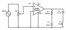
Looking at available ferrites something like this might do digikey (Fair-Rite 4077266011) or Mouser (Fair-Rite 4077276011) . Putting these into an online calculator [link] (Rod length 38mm; 6.35mm dia; Initial magnetic permeability 2000; Wire dia AWG-24; turns 17) gives an inductance of around 15 μH. Another calculator [link] states at 38 kHz an inductive reactance XL= 3.58 kΩ.
For a resonant LC circuit, yet more calculators [link] [link] suggests a 1.1 µF parallel capacitor to achieve resonance at around 39 kHz. with a characteristic impedance of 4 Ohms.
Because of the low duty cycle it might be possible to drive it push-pull from two output port pins (4 Ohm load!), or maybe use an op-amp arrangement per attached image. For sure some playing around will be required to optimise power coupling into the coil.
Attachments
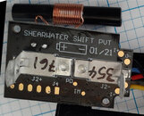
Awesome post.In the FCC documentation we can see a photo of the Swift coil (link)... it appears to be ~ 17 turns around a ferrite. I estimate the ferrite to be approximately 6.35mm diameter by 35mm length and the 'magnet wire' to be approximately 24 AWG (0.5mm dia), coil length around 8.5mm.
Been a very long time since I did any RF stuff so be warned I may be completely wrong but...
To get a high ‘Q’ factor in the 1 KHz to 1 MHz frequency range it is likely the ferrite is MnZn (Mix 31, 73, 75) with high permeability above 800 µ (plus fairly low volume resistivity and moderate saturation flux density).
Looking at available ferrites something like this might do digikey (Fair-Rite 4077266011) or Mouser (Fair-Rite 4077276011) . Putting these into an online calculator [link] (Rod length 38mm; 6.35mm dia; Initial magnetic permeability 2000; Wire dia AWG-24; turns 17) gives an inductance of around 15 μH. Another calculator [link] states at 38 kHz an inductive reactance XL= 3.58 kΩ.
For a resonant LC circuit, yet more calculators [link] [5] suggests a 1.1 µF parallel capacitor to achieve resonance at around 39 kHz. with a characteristic impedance of 4 Ohms.
Because of the low duty cycle it might be possible to drive it push-pull from two output port pins (4 Ohm load!), or maybe use an op-amp arrangement per attached image. For sure some playing around will be required to optimise power coupling into the coil.
moose_grunt
Contributor
I haven't been following as closlly as I should have...
Are you able to transmit a signal to the dive computer using an adrino/etc?
The idea floating around is to hook something up to the DPV that's transmitting to the perdix, setup a tank for 0-100bar and have a battery gauge on the perdix
Wouldnt need to be waterproof, it would be inside the DPV and could be powered off the DPV batt
This ends up being a thread hijack that could probably be split off, but...
There are a few projects floating around to use an arduino to read and transmit scooter data. The ones I've seen are mostly on the Dive X-tras X-Scooter Group on Facebook. As far as I know, none of them are using 38 khz to go to an AI-compatible computer, most are using plug-n-play RF modules to transmit data through the scooter hull and display on a LCD or OLED. My project (posted in the above FB group) uses 433 mhz lora modules from Adafruit, since they are readily available.
A word of warning: voltage is not a good indicator of remaining charge with lithium batteries, since they discharge on a curve. For example, my scooter battery is fully charged at 41v, and the cutoff is 30v. At a reading of 35v, that does not mean I have 50% remaining--it's closer to 25% remaining. The DiveX Piranha Smart Slice counts coulombs and shows amp hours used. Not sure about the Blacktips, since it only shows bars. The Genesis console shows voltage, watts, and watt hours (I believe), and likely counts coulombs as well to determine battery remaining.
All that being said, it would be a really cool project to display scooter information (or ppo2, as was earlier suggested) on your Shearwater! Now that the encoding is known, we just need to reverse-engineer a suitable transmitter assembly (suggestions for coil dimensions are already given above). At that point, the sky is the limit.
Keep up the good work, all!
Jim
TheScubaPanda
Contributor
Any chance someone could publish parts and diagram to make such a low freq RF emitter and receiver?
I'm a bit lost with the electronic side of it. I could help writing the code, but clearly I'm not getting anywhere on the HW side...
I'm a bit lost with the electronic side of it. I could help writing the code, but clearly I'm not getting anywhere on the HW side...
MadUKDiver
Registered
I've ordered some parts to build an antenna and have an Arduino UNO available from another project to run it. I'm going to start with the transmitter aspect and see if I can get it to work as that will be the simplest starting point.Any chance someone could publish parts and diagram to make such a low freq RF emitter and receiver?
I'm a bit lost with the electronic side of it. I could help writing the code, but clearly I'm not getting anywhere on the HW side...
I've bought a BD623 Motor Driver to buffer the output of the UNO. It has a bandwidth of over 100 kHz so hopefully up to the task and zero quiescent current in standby so might be useful in low power designs. It does require 6 volt supply though but my demo board has a 9v battery so will be ok for me. I'll be happy to share the hardware design if it works.
Once I have a transmitter running then I may look at the receiver side.
I'll have to re-acquaint myself with Arduino coding, do you have any experience on these?
Edit: BD6211 Motor Driver looks more promising, it works down to 3v supply.
TheScubaPanda
Contributor
Why do u need a motor driver ??? I don't get it ...I've ordered some parts to build an antenna and have an Arduino UNO available from another project to run it. I'm going to start with the transmitter aspect and see if I can get it to work as that will be the simplest starting point.
I've bought a BD623 Motor Driver to buffer the output of the UNO. It has a bandwidth of over 100 kHz so hopefully up to the task and zero quiescent current in standby so might be useful in low power designs. It does require 6 volt supply though but my demo board has a 9v battery so will be ok for me. I'll be happy to share the hardware design if it works.
Once I have a transmitter running then I may look at the receiver side.
I'll have to re-acquaint myself with Arduino coding, do you have any experience on these?
Edit: BD6211 Motor Driver looks more promising, it works down to 3v supply.
MadUKDiver
Registered
It is a cheap way of getting a low power H-Bridge driver. Instead of driving the antenna coil single sided (i.e. one side permanently to ground and the other switched to supply) an H-Bridge allows both sides of the antenna coil to be driven independently to supply or ground. This allows the current in the antenna coil to be driven in both directions, effectively doubling the EM flux. The ferrite antenna are very low Q and highly inefficient so an H-Bridge sounds like a good idea to increase radiated energy. It also provides flyback diodes and allows the antenna to 'float' such that the same antenna be used for transmit and receive (I've seen some promising starting points for a receiver circuit too). Of course it might not work at all.Why do u need a motor driver ??? I don't get it ...
I used to have access to lots of useful test equipment which would have made this development a lot easier. Right now it would be very handy to have an LCR meter and Signal Generator. All I have is an old, but good quality, analogue scope. Will be interesting to see how far I get... I've received two pieces of ferrite, the H-Bridge drivers should arrive soon. Just need to find time to install the Arduino IDE and re-acquaint with programming it again. Could take a while...

This thread (Question - Serial number prefixes on Pelagic Pressure Systems MH8A transmitters) brought my thinking back to the decoding topic.
I am wondering if it is possible that the transmitter code alpha prefixes might actually be encoded in what was being attributed to the preamble/sync bits.
If I recall correctly, the two transmitters that @rg422 used for the source data were the same brand, so would generate identical data in any brand/model prefix fields.
@rg422 what brand and alpha prefix were your transmitters?
Belzelbub
Contributor
I don't think it's likely that the alpha characters are used in the transmission. If they are, the computer ignores them as only the numeric is programmed into the DC when "pairing" to the transmitter.This thread (Question - Serial number prefixes on Pelagic Pressure Systems MH8A transmitters) brought my thinking back to the decoding topic.
I am wondering if it is possible that the transmitter code alpha prefixes might actually be encoded in what was being attributed to the preamble/sync bits.
Similar threads
- Replies
- 41
- Views
- 3,752
- Replies
- 2
- Views
- 371
- Replies
- 19
- Views
- 1,267
- Replies
- 14
- Views
- 2,766
- Replies
- 1
- Views
- 499
