You are using an out of date browser. It may not display this or other websites correctly.
You should upgrade or use an alternative browser.
You should upgrade or use an alternative browser.
Formula for compressor intake snorkel size
- Thread starter 2dogs
- Start date
Please register or login
Welcome to ScubaBoard, the world's largest scuba diving community. Registration is not required to read the forums, but we encourage you to join. Joining has its benefits and enables you to participate in the discussions.
Benefits of registering include
- Ability to post and comment on topics and discussions.
- A Free photo gallery to share your dive photos with the world.
- You can make this box go away
pescador775
Contributor
- Messages
- 2,652
- Reaction score
- 11
Try this calculator. For purposes of this device the sp grav of air is 1.0. Insert an extremely low pressure drop, eg 0.5 (2%) . Note that results are in cubic feet per hour. So, using a 5 cfm compressor, one could run a one inch pipe maybe 15 feet without much, if any, press drop, and a 1.5 inch pipe four times as far. All this probably ignores the suction and pulses of the compressor but maybe this thing is close enough if the right loss number is plugged in. Personally, I've tried one inch ID tubes as long as 12 feet on my Capitano and haven't noticed any drop in compressor output or other spooky effects like heat. Then again, that is all anecdotal.
Natural Gas Pipe Size Calculator
The folks at decostop, like "cool hardware", have some experience with big compressors and long intake pipes. Well, you haven't really said much about your problem so this may be an unwarranted presumption.
Natural Gas Pipe Size Calculator
The folks at decostop, like "cool hardware", have some experience with big compressors and long intake pipes. Well, you haven't really said much about your problem so this may be an unwarranted presumption.
Is there a relatively simple formula for the size to build an air intake snorkel for compressors?
Last edited:
I mainly deal with 5-7.5 scfm compressors and this is what we use for air intakes.
For every 10' of linear run, you must increase the diameter by one pipe size. Every 90 bend is considered one linear foot of run and there should be no more than 3 - 90's in the entire run. We generally tell folks to determine the largest pipe size and run that to within 5-10 feet of the compressor, then reduce to the intake size, which for our machines (5-7.5) is 1".
Craig
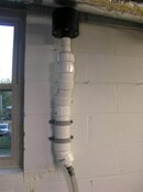
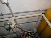
Thanks, that's a simple formula to work with. I'm wanting to verify the intake assembly is large enough to feed a K-14 Bauer pumping 10.5 CFM or 12cu.ft Free Air Delivery. The intake pre-cleaner can from Bauer, on the 1st stage of the compressor, has a 1" ID connection. There is a 3' piece of 1" reinforced vinyl tubing connecting to a 3" PVC canister that is 3' tall (this is to act as a "resevior" for air) and the silencer/filter (1.5" connection silencer/filter that's rated to flow 85 CFM ).sits atop that. (See attached pics.)
I built a in-line Tee with a vacum gauge but it just resonates as the air pulses back and forth so I wasn't sure it was accurate. Even added a needle valve to try and stop the pulsing but no luck.
Take a look at the pics and see what you think. Thanks for the help!
I built a in-line Tee with a vacum gauge but it just resonates as the air pulses back and forth so I wasn't sure it was accurate. Even added a needle valve to try and stop the pulsing but no luck.
Take a look at the pics and see what you think. Thanks for the help!
Attachments
pescador775
Contributor
- Messages
- 2,652
- Reaction score
- 11
Very sanitary and meticulous. I wouldn't bother with the vacuum gauge. Actually, I think there is a way that could be done with a ballast (accumulator) between the gauge and hose but it would be just for fun. There is plenty of experience around to help with your setup without the Mister Wizard aspect. But, that calculator is kind of fun to play with and I believe it gives a good estimate if the right inputs are used.
Use a manometer instead of a vacuum gauge. Most vacuum gauges are rated in inches of mercury, but manometers are usually used with water. Fill your manometer tube with plain ole water (add food coloring if your have old eyes) and it'll read far more accurately than a vacuum gauge. Manometers can be made easily with clear vinyl tubing attached to a board or piece of plywood.
A decent reading is less than 1-2 inches of water.
A decent reading is less than 1-2 inches of water.
Similar threads
- Replies
- 6
- Views
- 300
- Replies
- 5
- Views
- 299
- Replies
- 47
- Views
- 4,217


