DIY Gas analyzer

Please register or login

Welcome to ScubaBoard, the world's largest scuba diving community. Registration is not required to read the forums, but we encourage you to join. Joining has its benefits and enables you to participate in the discussions.

Benefits of registering include

  • Ability to post and comment on topics and discussions.
  • A Free photo gallery to share your dive photos with the world.
  • You can make this box go away

Joining is quick and easy. Log in or Register now!

I wouldn't worry about the cost of a He sensor. Those that want He analysis know it is expensive. But making something modular that starts with O2 and could add on easily modules for CO and He would be outstanding. It is what I suggested to Dive Nav for the new CooTwo. Just imagine small modules each containing a sensor that plug on to the end of the gas path. And no need to replace the whole analyzer if one component goes bad. I think it would instantly capture the market.
 
I've been tooling around with an arduino for this purpose. To calculate O2 store the air value in a variable, then divide current value by that variable and multiply by 20.9


Sent from my iPad using Tapatalk
 
The only thing I can find specific to this sensor model is http://www.viamed.co.uk/eng/Uploads/1A3100A6e6dA.pdfIt shows a schematic that does not include the center wire connected. Are you able to get a voltage output reading between the two outer pins on the connector only? See #11 on the specifications, required load 10K. Is a resistor supposed to be connected across the terminals? Any chance that you can deliver a known O2% different from ambient air and see if the sensor’s output changes?
 
Last edited:
Exhale into it, should be about 16% oxygen.

Most of us use the other type of sensor which uses a mono headphone cable so only two connectors.

And buy them from divegearexpress, their store brand come from a big manufacturer but are cheaper :)
 
modern analysers ( less energy consumption than heating gas ) measures He via ultrasound NRC International have find some interesting link
Product line but i don't know price for tube
Thats an interesting sensor, but couldn't find anyone that sells them, and my guess is they costs more than I am willing to spend on this project.


Exhale into it, should be about 16% oxygen.
Most of us use the other type of sensor which uses a mono headphone cable so only two connectors.
And buy them from divegearexpress, their store brand come from a big manufacturer but are cheaper
Right now I hyperventilating into a plastic bag and use that as a test gas.

The only thing I can find specific to this sensor model is Object not found! shows a schematic that does not include the center wire connected. Are you able to get a voltage output reading between the two outer pins on the connector only? See #11 on the specifications, required load 10K. Is a resistor supposed to be connected across the terminals? Any chance that you can deliver a known O2% different from ambient air and see if the sensor’s output changes?
Thank you for the information :)


Todays update:
I went back to plan A and used 5v as the referance voltage, using a LM358 opamp, 330Ω resistor and a 1.5Ω resistor to create an no inverted amplifier circuit with a gain of 221, to aplifie the signal from the O2 sensor from 0-20mV to 0-4.42v. Using a referance voltage of 1.1v made the CO sensor act funny.
Fil 05.08.15, 17.16.04.jpg
 
Understanding your reading is very simple. The output is linear with the O2 concentration, so just adjust for 20.9% with air. It will depend on temperature, so you'll need a calibration button like other nitrox analyzers. Here is a fantizillion of diy nitrox analyer constructions out there to get inspiration from. And it couldn't be simpler, when the output is simply proportional to O2. About making a helium analyzer, that is much more fun. A very cheap way to make it is by analyzing speed of sound. very cheap sensors: (A resonant chamber, mic capsule and speaker) And then a lot of calculations :) Some analyzers do it this way, but only from one brand due to a patent.
 
Just amplifying the O2 cell's level is not the _right_ way to read it. It works somewhat, and a lot of the el Cheapo analyzers use that method, but it's not the correct loading for the cell to work as spec'd. There's a more elegant way to do it, and it ensures your reading is a lot more accurate.

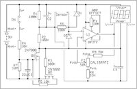
To get it right, you really want to stabilize the cell with a constant load of 100K across it regardless of calibration. Attached is a standalone schematic of an analog oxygen analyzer (not mine, source now lost, but I built a similar circuit...) It demonstrates the proper way to set up the circuit. If you ignore the on/off circuitry on the left side -- this meter turns on with a SPST pushbutton and automatically turns off whenever the voltage across the R/C network pulls the FETs low -- the rest of the schematic illustrates the proper construction for providing the right load to the O2 cell.

Diodes D1 & D2 protect and ensure that the input of the op amp can never exceed the supply rails by more than the diode's drop voltage - about .6V.

C2 & C3 are for decoupling the supplies to minimize electrical noise etc. Especially using a microcontroller, you need these.

The amplifier output voltage will always drive to a voltage level that results in the voltages at pins 2 and 3 being equal. The voltage at pin 2 is attenuated by the network R8, R9 and P2 and it is the combinations of these that determine the gain of the amplifier.

The lowest gain is given by: (R8+R9+P)/(R8+P), whilst the highest gain is: (R8+R9+P)/R8.

To optimize, the starting point for values of resistors will always be the value of potentiometer P2, as the available values are limited, typically 10K, 20K 50K or 100K. You'll then need to establish the maximum and minimum gains, AH & AL; i.e. AH = 20.9/Vmin and AL = 20.9/Vmax where Vmin & Vmax are the limits of the sensor output quoted on the datasheet. Usually for an R-17 type cell, this is 7 and 17 mV, respectively.

You can now insert these figures into the formulas below:
R8=(AL*P2)/(AH-AL)
R9=(P2+R8)*(AL-1)

Doing it this way gives you a straight reading on the voltmeter, so no math required in software. If you are using an A-D converter in the chip to do your reading, you'd scale the amplifier for 100% O2 on a fresh cell giving you a full-scale reading of your reference voltage instead of targeting 1V full-scale to get the best resolution.
 

Attachments

  • O2.jpg
    O2.jpg
    34.1 KB · Views: 418
Just amplifying the O2 cell's level is not the _right_ way to read it. It works somewhat, and a lot of the el Cheapo analyzers use that method..

Well.. your circuit just amplifies the cell's level. Nothing special. And offsets it to make it work with a precision, non rail to rail opamp.
But it looks like it would work fine.
Great that you bring a schematic.

Best Regards, Eskil
 
If you want to use the 5v ref, you can eliminate the opamp by using the Adruino Due which has 12 bit resolution or a Teensy 3.1 which has 16 bit resolution.

2^12 = 4096 bits
5v / 4096 bits = 0.00122070312 volts

In other word that would allow the Analog to Digital Converter to read 1.22 millivolts.


On a different note I have done a little research into helium analyzers and came across this thermal conductivity sensor. It has a sealed reference gas (air) and it compares it to the gas you are testing. It then outputs either a pos or neg millivolt reading based off the difference in thermal conductivity.

At $59 it seems like a reasonable option to try. The documentation does say that the readings are non-linear so an equation of some sort would be needed to get the correct output at all gas percentages. The main site does provide documents with equations but I haven't really sat down and tried to fully comprehend them. Under the search filter just put the target gas as helium and the technology as thermal conductivity.
 

Back
Top Bottom