The idea popped up in my mind to have remote monitoring of the banked-air pressure.
So in one hand I have an internet cable, in the other hand a fill whip connected to several 50 liter tanks. Since there's no internet connectivity on a tank (yet), I had to think of something in between.
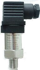
So first something to measure the pressure. Industrial pressure transducers use the 4-20mA current loop. Advantage is that the cables to the transducer can be very long, the voltage may drop over distance, but the current stays stable. Characteristics:
0mA = fault, cable break, power failure, other problem
4mA = zero pressure
20mA = max pressure
The easiest and cheapest device to measure values with, is a Raspberry Pi. The RPi is capable of measuring digital signals, so that current between 4mA and 20mA has to be converted.
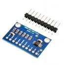
The ADS1115 module can convert a voltage between 0V - 5V to a 16 bits value that the RPi can read. However the transducer outputs a current, not a voltage.
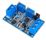
To convert that current into a voltage, another converter module is put in between.
The components I used are these:
US $26.1 |0 0.2 60Mpa Silicon Pressure Transmitter Pressure Transducer G1/4 4 20mA output|output| | - AliExpress - transducer
US $1.71 5% OFF|16 Bit I2C ADS1115 Module ADC 4 channel with Pro Gain Amplifier RPi 1PCS|board spinner|board pants|board lens - AliExpress - A/D converter
US $1.0 |Current To Voltage Module 0 20mA/4 20mA to 0 3.3V/0 5V/0 10V Voltage Transmitter Signal Converter Module|Integrated Circuits| | - AliExpress - mA/V converter
I started with some left-over materials to connect the transducer to a tank:
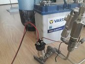
To create the 4-20mA current loop, a power supply is needed, I used a car battery that was standing in a corner doing nothing.
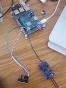
The two wires from the transducer connect to the mA/V converter (lower right device in the picture), a signal wire from this converter goes to the A/D converter (red wire to the lower left device in the picture), and from the A/D converter two wires go to the RPi (I2C bus). The other wires are 3.3V power supply for the converters.
That was the hardware part. The software part took me a little longer, but I always assume someone else invented the wheel already, so it's just a matter of looking for that specific wheel on the internet. In a nutshell:
- install Raspbian on the RPI and update the software
- install the adafruit-circuitpython-ads1x15 software library
- create a python3 script to read the digital output value:
I finally managed to get the whole setup working, so the next step was installing it on the supply line of the bank air tanks.
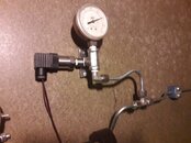
The final step was calibrating the mA/V converter. One potmeter sets the output voltage at zero Volts when the current loop supplies 4mA, the other potmeter is to set a maximum voltage at maximum pressure.
Having done that, I used a digital pressure gauge the measure the exact pressure, starting with the maximum pressure and then in steps of 20bar (~290psi) down to zero. Each pressure measured shows a digital value that the script spits out on the screen, and dividing that value by the measured pressure shows (roughly) the same constant on every measurement. In my case 0.01042 and that's the value that is set in the script.
Final part: measuring. MRTG is a really simple tool that measures two values every 5 minutes and draws a graph of these values over time. With this result:

The compressor ran yesterday around 13:45, increasing the pressure of all the tanks up to 240bar. Today I can see that there's somewhere a small leak, something to fix in the coming week.
So in one hand I have an internet cable, in the other hand a fill whip connected to several 50 liter tanks. Since there's no internet connectivity on a tank (yet), I had to think of something in between.

So first something to measure the pressure. Industrial pressure transducers use the 4-20mA current loop. Advantage is that the cables to the transducer can be very long, the voltage may drop over distance, but the current stays stable. Characteristics:
0mA = fault, cable break, power failure, other problem
4mA = zero pressure
20mA = max pressure
The easiest and cheapest device to measure values with, is a Raspberry Pi. The RPi is capable of measuring digital signals, so that current between 4mA and 20mA has to be converted.

The ADS1115 module can convert a voltage between 0V - 5V to a 16 bits value that the RPi can read. However the transducer outputs a current, not a voltage.

To convert that current into a voltage, another converter module is put in between.
The components I used are these:
US $26.1 |0 0.2 60Mpa Silicon Pressure Transmitter Pressure Transducer G1/4 4 20mA output|output| | - AliExpress - transducer
US $1.71 5% OFF|16 Bit I2C ADS1115 Module ADC 4 channel with Pro Gain Amplifier RPi 1PCS|board spinner|board pants|board lens - AliExpress - A/D converter
US $1.0 |Current To Voltage Module 0 20mA/4 20mA to 0 3.3V/0 5V/0 10V Voltage Transmitter Signal Converter Module|Integrated Circuits| | - AliExpress - mA/V converter
I started with some left-over materials to connect the transducer to a tank:

To create the 4-20mA current loop, a power supply is needed, I used a car battery that was standing in a corner doing nothing.

The two wires from the transducer connect to the mA/V converter (lower right device in the picture), a signal wire from this converter goes to the A/D converter (red wire to the lower left device in the picture), and from the A/D converter two wires go to the RPi (I2C bus). The other wires are 3.3V power supply for the converters.
That was the hardware part. The software part took me a little longer, but I always assume someone else invented the wheel already, so it's just a matter of looking for that specific wheel on the internet. In a nutshell:
- install Raspbian on the RPI and update the software
- install the adafruit-circuitpython-ads1x15 software library
- create a python3 script to read the digital output value:
Code:
import time
import board
import busio
import adafruit_ads1x15.ads1115 as ADS
from adafruit_ads1x15.analog_in import AnalogIn
i2c = busio.I2C(board.SCL, board.SDA)
ads = ADS.ADS1115(i2c)
chan = AnalogIn(ads, ADS.P0)
pressure = chan.voltage/0.01042
print(pressure)
I finally managed to get the whole setup working, so the next step was installing it on the supply line of the bank air tanks.

The final step was calibrating the mA/V converter. One potmeter sets the output voltage at zero Volts when the current loop supplies 4mA, the other potmeter is to set a maximum voltage at maximum pressure.
Having done that, I used a digital pressure gauge the measure the exact pressure, starting with the maximum pressure and then in steps of 20bar (~290psi) down to zero. Each pressure measured shows a digital value that the script spits out on the screen, and dividing that value by the measured pressure shows (roughly) the same constant on every measurement. In my case 0.01042 and that's the value that is set in the script.
Final part: measuring. MRTG is a really simple tool that measures two values every 5 minutes and draws a graph of these values over time. With this result:
The compressor ran yesterday around 13:45, increasing the pressure of all the tanks up to 240bar. Today I can see that there's somewhere a small leak, something to fix in the coming week.


