You are using an out of date browser. It may not display this or other websites correctly.
You should upgrade or use an alternative browser.
You should upgrade or use an alternative browser.
Laser Cutting - drawings
- Thread starter АлександрД
- Start date
Please register or login

Welcome to ScubaBoard, the world's largest scuba diving community. Registration is not required to read the forums, but we encourage you to join. Joining has its benefits and enables you to participate in the discussions.
Benefits of registering include
- Ability to post and comment on topics and discussions.
- A Free photo gallery to share your dive photos with the world.
- You can make this box go away
OP
АлександрД
Contributor
@АлександрД
Thank you for the contributions. Do you have .DXF files for these parts? AutoCAD .DWG files are great for people with a program that can read them (same or newer version) because they can edit them for their purpose. The advantage of .DXFs is they can be sent directly to a laser or waterjet service company and can be imported or converted by a lot more programs.
Thank you for the contributions. Do you have .DXF files for these parts? AutoCAD .DWG files are great for people with a program that can read them (same or newer version) because they can edit them for their purpose. The advantage of .DXFs is they can be sent directly to a laser or waterjet service company and can be imported or converted by a lot more programs.
OP
АлександрД
Contributor
sorry, I have not any verctor graphics programs at this moment to convert it...
But I have .cdr files, if you like. can share it. see below.
Our laser-cutting company, where I`d ordered buckles on the photo above - they asked just dwg files. Than ajusted it to their internal format.
It should be reworked in the company, due to buckles placement on the leaf, to save matherial.
But I have .cdr files, if you like. can share it. see below.
Our laser-cutting company, where I`d ordered buckles on the photo above - they asked just dwg files. Than ajusted it to their internal format.
It should be reworked in the company, due to buckles placement on the leaf, to save matherial.
Attachments
Our laser-cutting company, where I`d ordered buckles on the photo above - they asked just dwg files. Than ajusted it to their internal format.
It should be reworked in the company, due to buckles placement on the leaf, to save matherial.
Interesting. I have used CNC laser, waterjet, and plasma cutting services in the US and they all took my .DXF files. Their software automatically analyzed all the different shapes and quantities and "auto-nested" parts on the base material. They could even auto-nest smaller parts inside other large parts after the waste areas were ID'd by the operator. It also offset the cutting path inside the .DXF perimeter by the kerf width. Most systems would automatically guess what areas were internal waste and have the operator manually verify each part before auto-nesting the entire job.
Several systems allowed them to put a sheet on the table that already had parts cut off and an optical head will scan the outer edges, even if they were irregular. That outline could be selected for the base of their auto-nesting software.
Many also had a library of shapes for specific industries, like HVAC ducting. Very cool stuff with a much simpler interface than AutoCAD. Generally they weren't great at creating shapes beyond choosing fonts and sizes of alphanumeric characters, but that is what CAD programs like AutoCAD is for.
The Chairman
Chairman of the Board
Very cool stuff.
fibrefab2
Registered
I use AutoCAD for my designs. I'm not a trained drafty, just have access to YouTube!
I've made a few side mount brackets, along with D rings and sliders.
My local laser cutter is happy to accept the .dwg files, the only problem is there is a minimum spend of $88 !
I'll pop a few picks up when I get the chance.
I've made a few side mount brackets, along with D rings and sliders.
My local laser cutter is happy to accept the .dwg files, the only problem is there is a minimum spend of $88 !
I'll pop a few picks up when I get the chance.
fibrefab2
Registered
As promised
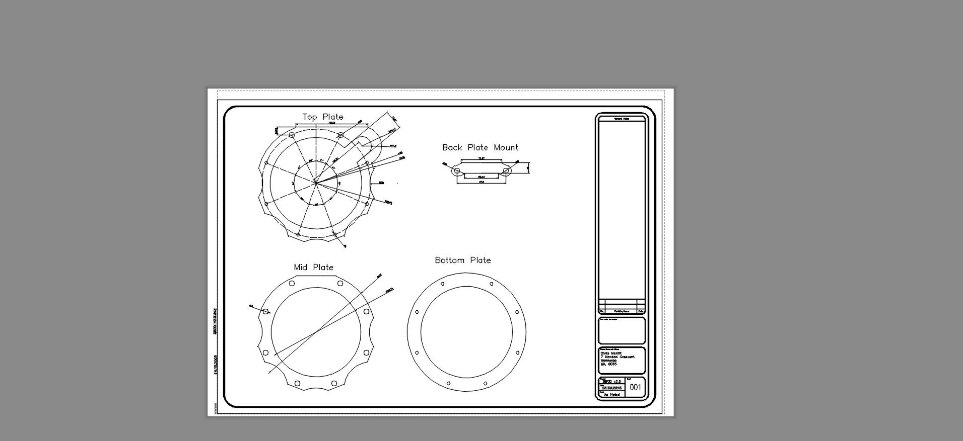
Below is a design, classed as a work in progress that I plan to use to house my rebreather.
A basic triglide

Below is a design, classed as a work in progress that I plan to use to house my rebreather.
A basic triglide
fibrefab2
Registered
sidemount buckles
View attachment 525334
double D-ring buckle
View attachment 525337
single D-ring buckle
View attachment 525339
looks like this:
View attachment 525343
View attachment 525344
I'm interested in why you use 3 slots in the D-rings ?
OP
АлександрД
Contributor
Just in caseI'm interested in why you use 3 slots in the D-rings ?
")
With tree cuts you have some more flexibility for different use of this buckles.
As idea - it was to add extra D-ring in middle slot
Similar threads
- Replies
- 0
- Views
- 116
- Replies
- 0
- Views
- 155
- Replies
- 0
- Views
- 645